AMAZON multi-meters discounts AMAZON oscilloscope discounts
The management of fuel is essential for the safe and economic operation of aircraft. The scope of fuel management depends on the size and type of air craft; fuel is delivered to the engines using a variety of methods. The system comprises fuel quantity indication, distribution, refueling, defueling and fuel jettison. On a typical passenger aircraft, the fuel is contained within the sealed wing box structure. The fuel tanks are divided into main tanks, reserve tanks and center wing tanks. Fuel tanks on general aviation (GA) aircraft are rubberized bags (bladder tanks) contained within the structure of the aircraft; smaller GA aircraft use metal fuel tanks attached to the wings and/or fuselage.
In the first instance, we need to measure the quantity of fuel on board the aircraft. Various technologies and methods are used to measure fuel quantity: this depends mainly on the type and size of aircraft.
Technologies range from sight gauges through to electronic sensors. On larger aircraft, fuel is fed to the engines by electrically driven pumps. On smaller aircraft, an engine-driven pump is used with electrical pumps used as back-up devices. Solenoid or motorized valves are used to isolate the fuel supply to engines under abnormal conditions. On larger aircraft, the fuel can be transferred between tanks; this is controlled manually by the crew, automatically by a fuel control computer. This section provides an over view of fuel management on a range of aircraft types.
1. Storage overview
Rigid tanks are usually found in smaller general aviation aircraft. They are installed within the fuselage and/or wings, and are designed to be removable for inspection, replacement, or repair. They do not form an integral part of the aircraft structure.
Bladder tanks are reinforced rubberized bags installed within specific areas of aircraft structure. The bladder can be inserted/removed via the fuel filler inlet or a dedicated access panel; the bladder is then secured to the airframe by clips inside the compartment.
Integral fuel tanks are located within the structure on larger aircraft; these are sealed to accommodate fuel storage. These tanks form part of the aircraft structure; they cannot be removed for service or inspection. Access panels are installed to allow internal inspection, repair, and servicing. On large passenger aircraft, there are four main tanks, two in each wing. The area between the forward and aft spars is divided into tank sections by solid ribs. The wing skin (upper and lower surfaces) completes the tank. Wing ribs act as baffles to prevent the fuel from ' sloshing ' around the tank. The inter-spar area of the wing center section is also used to store fuel. This center wing tank is similar in construction to the main tanks.
2. Fuel quantity measurement and indication
Various technologies and methods are used to measure and display fuel quantity: this depends mainly on the type and size of aircraft. The fuel quantity methods described here could equally apply to other fluids, e.g. oil, hydraulic fluid or water. Some of the methods used are not actually part of an electrical system; however, they are described here to provide a complete review of the methods employed across a range of aircraft types. The methods used for measuring fuel quantity can be summarized as:
-- sight glass
-- float gauge
--resistance gauge
-- under-wing measurement
-- capacitance units
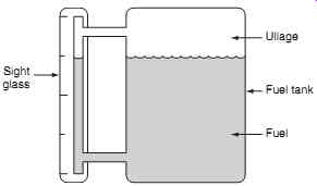
FIG. 1 Fuel quantity sight glass
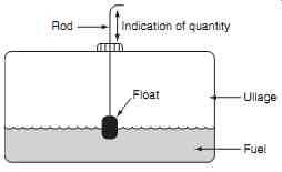
FIG. 2 Fuel quantity float gauge
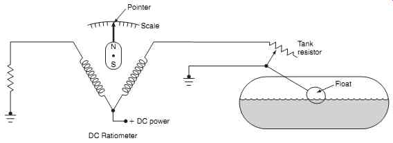
FIG. 3 Fuel quantity float valve
2.1 Sight glass
The sight glass method illustrated in FIG. 1 is based on a simple glass or plastic tube located on the outside of the tank, and visible to the pilot. Fluid level in the tube is the same as the level in the tank; graduations on the tube provide an indication of tank contents. The advantage of this method is that it has no moving parts and is suitable for fuel or oil. This method is suitable for small aircraft where the pilot can see the sight glass; alternatively it is suited for ground serving applications.
Key point: The space above the fuel in a storage tank is called the ullage.
2.2 Float gauge
The float gauge uses a rod projecting through a hole in the tank cap; see FIG. 2. A float is attached to the base of the rod and this rises and falls with the fuel level. The pilot checks the amount of rod protruding through the cap and this provides a direct reading of fuel quantity. One disadvantage of this method is that it is not very stable during aircraft maneuvers.
The majority of small general aviation (GA) aircraft use a float gauge system similar to that used in motor vehicles as shown in FIG. 3; this is based on a float connected to a variable resistor adjacent to the tank.
The variable resistor is connected into a DC ratiometer circuit where two opposing magnetic fields are created in each of the coils. The pointer is formed with a permanent magnet and is aligned with the resulting magnetic field created by the coils; the pointer moves in accordance with the ratio of currents in the coil.
Key point: The DC ratiometer pointer position is not adversely affected by variations in power supply voltage.
2.3 Under-wing measurement
Under-wing measurement of fuel quantity is used during ground servicing only. The drip stick method uses a hollow tube pushed into the tank. During flight, the tube is stowed into a latched position, which is flush with the aircraft wing or fuselage surface. To take a reading, the tube is released from its stowed position and slowly withdrawn from the tank; when fuel starts to drip from the tank, a reading is taken from graduations on the tube.
Key maintenance point: Spilt fuel presents a fire hazard; take all necessary precautions to clean up any spillage and dispose of any rags soaked in fuel.
A safer alternative to the drip stick method utilizes a transparent plastic rod. This method uses the principle of light refraction, and is based on fuel and air having different refractive indexes. When the tip of the rod is moved above/below the surface of the fuel, the light intensity emerging from the viewing end of the rod changes. A reading is then taken from graduations on the rod.
Another version of the under-wing fuel gauge uses a floatstick that comprises a rod, float and magnets located inside the tank as shown in FIG. 4. The floatstick is stowed when not in use and released via a quarter-turn cam mechanism; it slides out of the tank until the two magnets align and is then retained in this position. The floatstick is moved in and out of the tank until the attraction of the magnets can be sensed. The fuel quantity reading is then taken from a reference point on the surface of the wing. When the reading has been taken, the rod is pushed back and locked into the stowed position.
Floatsticks can be used when the electronic fuel quantity system (see capacitive fuel quantity system) is unserviceable. All floatsticks are read for each tank and the measurements recorded, the quantity is then calculated from tables in the aircraft documentation.
A typical medium-sized aircraft has six floatsticks in each wing tank and four in the center tank.
Key point: Under-wing fuel quantity measurements are used during ground servicing only.
=====
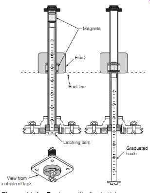
FIG. 4 Fuel quantity float stick
Magnets; Float; Fuel line; Latching cam; View from outside of tank; Graduated scale
=====
Right main tank; Center tank; Left main tank
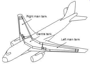
FIG. 5 Integral fuel tanks
Inner 'plate'; Outer 'plate'; Electrical wiring loom and connector
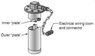
FIG. 6 Capacitance fuel quantity system - sensor
=====
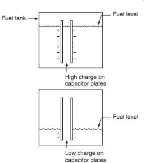
FIG. 7 Capacitance fuel quantity system - principles
Fuel tank; Fuel level; High charge on capacitor plates
Fuel level; Low charge on capacitor plates
=====
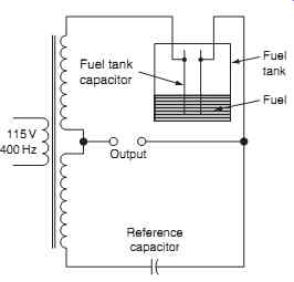
FIG. 8 Capacitance fuel quantity system - impedance bridge circuit
115V 400Hz Output Fuel; Fuel tank; Fuel tank capacitor; Reference capacitor
======
2.4 Capacitive fuel quantity system
The majority of turbine-powered aircraft fuel quantity indicating systems (FQIS) use the capacitive fuel quantity system. On a typical twin-engine passenger aircraft the fuel tanks are contained within the aircraft structure as shown in FIG. 5. Fuel tank sensors are located throughout each tank and are monitored by an electronic control system. Accurate readings can be obtained by capacitive fuel quantity systems in large and irregular-shaped tanks.
2.4.1 Principle of operation
Fuel tank units are formed by concentric aluminum tubes; the inner and outer tubes are the capacitor plates, see FIG. 6. The primary advantages of this technology are no moving parts and fuel quantity is measured in mass rather than volume. (The mass of fuel determines the amount of energy available.) The dielectric is either fuel or air depending on the quantity of fuel in tank. Air has a dielectric of 1.0006 (practically unity); fuel has a dielectric of approximately two; this provides a good relationship for the measurement of a variable quantity.
From basic fundamentals, we know that capacitance is proportional to:
-- plate area
-- air gap
-- dielectric strength
In the capacitive tank unit, the first two parameters are fixed; the capacitance varies in accordance with the dielectric, i.e. the amount of fuel in the tank as illustrated in FIG. 7. With a high quantity of fuel in the tank, the capacitance is high; capacitance varies in direct proportion to the amount of fuel in the tank.
The tank's capacitance unit is connected into an impedance bridge circuit, see FIG. 8. Variation in capacitance ( C ) of the fuel tank unit causes a change in reactance ( XC ); this is given by the formula: XFC C _ 1 2 p
...where XC is the reactance, ? is a constant, F is the frequency (400 Hz from the aircraft power supply) and C is the capacitance. The impedance ( Z ) of a capacitive network can be calculated from the formula: ZRX __ v( 22 c )
The current in a capacitive network can now be calculated from the formula: I V Z
When the fuel is consumed during a flight, and the fuel level decreases, the capacitance decreases and the reactance increases; less current flows in the tank unit (compared with the reference capacitor). This unbalance causes a potential difference at points X-Y, proportional to fuel quantity; this signal is amplified and used to drive an indicator. Capacitance trimmers are used for calibration of the fuel indicators (or gauges).
Key point: Air and fuel have dielectrics of approximately unity and two respectively.
2.4.2 Density compensation
The volume of fuel in a tank varies with temperature; as the temperature changes, the mass of fuel remains the same, but the volume changes. The dielectric is therefore affected by fuel density; this density will change with temperature. Increased density is a result of reduced temperature that will cause increased capacitance. Changes in fuel density are measured by a compensation unit. This is an additional tank unit located in the bottom of the fuel tank, therefore it is always immersed in fuel. The compensating unit is connected into the impedance bridge such that changes in fuel density cause the bridge to become unbalanced and this compensates for the change in fuel level.
Key point: The volume of fuel in a tank varies with temperature; as the temperature changes, the mass of fuel remains the same, but the volume changes.
==========
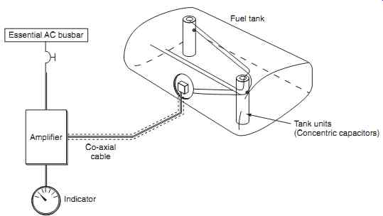
FIG. 9 Capacitance fuel quantity system - multiple tank units
Tank units (Concentric capacitors); Fuel tank; Co-axial cable; Amplifier; Essential AC busbar; Indicator
==========
2.4.3 Multiple tanks
Multiple tank units are often employed in larger air craft as illustrated in FIG. 9. On a typical medium sized passenger aircraft there are twelve capacitive tank units in each main fuel tank, and nine in the center fuel tank. The construction of all the tank units is the same, except for their length; this depends on the depth of the tank at that particular location. Each tank unit consists of two concentric aluminum tubes and a terminal block. The aluminum tubes are anodized and polyurethane coated to protect against corrosion.
The air gap between the tubes is relatively wide to avoid electrical short-circuiting, caused by contamination in the fuel or fungus coating on the tubes.
Key maintenance point: The fuel tank units are factory calibrated and can not be adjusted on the aircraft.
A tank unit wiring harness attaches to the terminal block of the tank unit. The terminals on the tank wiring harness and the terminal posts have different dimensions to prevent cross-connection during installation. Tank unit end caps are insulated to ensure that the unit does not short to the ground; they also control stray capacitance that forms between the tank unit and ground plane ( capacitance fringing ). Two brackets made of nonferrous glass-filled nylon attach each tank unit to the fuel tank structure.
Intrinsic safety is a technique used for safe operation of electrical and electronic equipment in explosive atmospheres. It is essential that the available electrical and thermal energy in the fuel quantity system is always low enough that ignition of the hazardous atmosphere cannot occur.
Key maintenance point: When working with fuel systems, always use intrinsically safe lamps or torches.
3. Fuel feed and distribution
GA aircraft are normally fitted with an engine-driven pump (EDP), with electrical boost pumps fitted to prime the system during starting. The electrical boost pumps also provide fuel pressure should the EDP fail.
A simple fuel pump system comprises an electrically driven boost pump motor controlled by an on/off switch; see FIG. 10.
This system is enhanced by a two-stage throttle control system, as illustrated in FIG. 11. When the boost pump selector switch is set at the 'low' setting, electrical power is switched through the resistor and the motor runs at a low speed. With the engine running, the selector is moved to the ' high ' setting; this provides power through the normally closed (NC) contacts of the throttle micro-switch. When the throttle is set below one-third open, the resistor remains in series, and the motor continues to run at the low speed.
When the throttle is advanced, the throttle micro switch changes over via the normally open (NO) contacts to bypass the resistor and apply full power to motor.
The typical fuel feed arrangement on a medium- to large-sized passenger aircraft comprises two booster pumps for each main tank; the motor is located on the tank bulkhead, with the pump located inside the tank. The fuel distribution system requires electrical power and is controlled by a panel in the flight compartment as illustrated in FIG. Fuel shut-off valves are connected to the battery bus, and controlled by the engine start lever (see engine systems, Section 10) and fire handle (see fire protection, Section 16). The fuel system normally has the means of transfer ring fuel between tanks (see fuel transfer); this is controlled by a selector switch that operates a cross feed valve. Each boost pump is driven by a 115 V AC three-phase motor selected on/off on the control panel via a relay.
The delivery output from each pump feeds into the system via a non-return valve (NRV). Under normal operating conditions, each pump feeds own engine via a motor driven low-pressure (LP) cock. If a center tank is fitted as part of a three-tank installation, this can feed either engine by a fuel transfer system as shown. On some aircraft, tank pumps are located in a dry area of the wing root; on other aircraft the pumps are actually inside the fuel tank. In the latter case, the crew have to maintain certain minimum fuel levels. Control switches for all pumps, cocks and valves together with warning indications are located on the overhead panel or the flight engineer's station.
LP cocks are automatically closed if the fire handle is activated.
=====
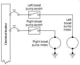
FIG. 10 Simple fuel pump system
Left boost pump switch; Right boost pump switch; Right boost pump motor; Left boost pump motor; Electrical busbar
=====
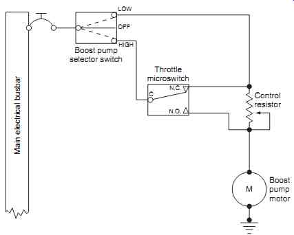
FIG. 11 Two-stage fuel pump system
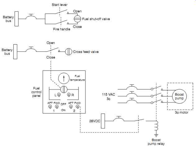
FIG. 12 Fuel distribution system - electrical power
===
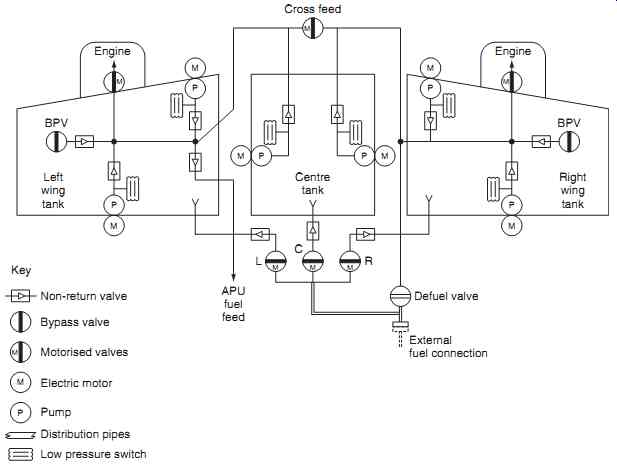
FIG. 13 Fuel distribution - three-tank system
M P Electric motor; Pump; Distribution pipes; Low pressure switch; M Non-return valve Bypass valve Motorized valves Key
===
Key maintenance point: Leaving a fuel pump switched on with low fuel quantity is an explosion risk since the pump is likely to overheat.
Key maintenance point: If a pump is left running dry for extended periods, typically 10 minutes, it will have insufficient fuel for priming which will render it inoperative when the tank is subsequently refueled.
4. Fuel transfer
This system is used to selectively transfer fuel between tanks; electrically driven fuel pumps and motorized valves are controlled either manually by the crew or by an automatic control system. A simple example of this is illustrated in FIG. 13, where fuel can be cross-fed between the left and right tanks.
On larger aircraft, the complexity of this fuel transfer system increases. The system comprises a number of motorized valves. Engine valves are activated by the start lever or fire handles. The left, center and right refuel/defuel valves are operated from an under-wing panel. Bypass valves (BPV) are operated if an electrical pump's fuel filter is blocked. (The BPV senses differential pressure across the filter.) Controls and indications are located on an overhead panel or flight engineer's station. An electrically operated cross-feed valve normally closed unless fuel is being transferred.
It is essential that fuel temperature is monitored, either manually or automatically. The maximum fuel temperature is typically _ 49°C; the minimum fuel temperature is -45ºC or freezing point _ 3ºC, whichever is higher; the typical freezing point of Jet A1 fuel is _ 47ºC. Fuel temperature is measured by an RTD. If the fuel temperature is approaching the lower limits, some fuel could be transferred between tanks; alternatively the aircraft would have to descend into warmer air or accelerate to increase the kinetic heating.
5. Refueling and defueling
A refueling control panel and pressure connections are normally located in one or both of the wing areas allowing the fuel to be supplied directly into the main fuel system. A bonding lead is always connected between the fuel bowser and aircraft to minimize the risk of static discharge. The fuel tank supply line is connected to the aircraft and pressure applied. Selective control of the system's motorized valves allow specific tanks to be filled as required.
Defueling is often required before maintenance, or if the aircraft is to be weighed. The fuel is transferred from the aircraft into a suitable container, typically a fuel bowser. This is achieved via a defueling valve and applying suction through valves.
6. Fuel jettison
When an aircraft takes off fully loaded with passengers and fuel, and then needs to make an emergency landing, it will almost certainly be over its maximum landing weight. Fuel has to be disposed of to reduce the aircraft weight to prepare for the emergency landing. A large aircraft such as the Boeing 747 can be carrying over 100 tonnes of fuel; this is almost 50% of the aircraft's gross weight. One way of burning off fuel and reducing aircraft weight is to fly in a high drag configuration, e.g. 250 knots with the gear down (speed-brakes will further increase the drag). Aircraft can be certified for landings up to the maximum takeoff weight (MTOW) in an emergency; however, overweight landings would only be made if burning off fuel exposed the aircraft to additional hazards.
Some aircraft are installed with a fuel jettison, or fuel dumping system . This provides a means of pumping fuel overboard to rapidly decrease the aircraft's weight. Fuel can normally be jettisoned with landing gear and/or flaps extended. Two jettison pumps are installed in each main tank, fuel is pumped via a jettison manifold to nozzle valves located at each wing tip trailing edge.
Key maintenance point: Bonding of fuel system components is essential to ensure intrinsic safety.
7. Fuel tank venting
The venting system takes ram air from intakes on the underside of the wing for two specific purposes.
When the aircraft is flying, ram air is used to pressurize the fuel to prevent vaporization at lower atmospheric pressures. The ram air also pressurizes the fuel tanks to ensure positive pressure on the inlet ports of each pump. The expansion space above the fuel, called ullage, changes with aircraft attitude. Float operated vent valves are located at Key points in the tank to allow fuel to escape into the vent system.
Venting tanks (sometimes called surge tanks ) in the wing tips collect this overspill from the main tanks; the fuel is then pumped back into one of the main tanks. Float-operated vent valves prevent inadvertent transfer of fuel between the tanks.
========
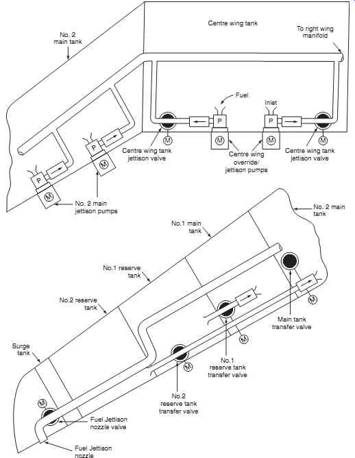
FIG. 14 Fuel jettison system schematic; No. 2 main tank
To right wing manifold Surge tank No.2 reserve tank No.1 reserve tank No.1 main tank Inlet Fuel Center wing tank Center wing tank jettison valve No. 2 main jettison pumps No. 2 main tank Main tank transfer valve No.1 reserve tank transfer valve No.2 reserve tank transfer valve Fuel Jettison nozzle valve Fuel Jettison nozzle Center wing tank jettison valve Center wing override/ jettison pumps
========
8. Fuel tank inerting
Aircraft have been destroyed due to explosions in empty center wing fuel tanks. The most likely cause is the center tank fuel pumps being left running in high ambient temperatures with low fuel quantity. The first center wing tank (CWT) explosion on a large passenger aircraft occurred on a B707 in 1959; there have been other events in more recent times. In May 1990, shortly after pushback, the center wing tank (CWT) exploded on a Philippine Airlines Boeing 737, killing eight people. The CWT had not been filled since March 9, 1990. Air-conditioning (A/C) packs had been running on the ground before pushback for approximately 30 to 45 minutes, ambient air was 35°C/95°F. On March 3, 2001, the center wing tank explosion on Thai Airways International B737 was followed 18 minutes later by an explosion in the right wing tank. Residual fuel was in the CWT. Air-conditioning packs had been running continuously since the air craft's previous flight, including some 40 minutes on the ground. Ambient air temperature was in excess of 30°C. On July 17, 1996, the CWT exploded on a TWA B747-100 shortly after takeoff from JFK International Airport with fatal consequences. The CWT contained a low amount of residual fuel. The A/C packs had been running on the ground for 2.5 hours before takeoff, ambient temperature was 28°C/82°F. These three fatal CWT fuel-tank explosions all had certain elements in common:
-- all three aircraft had only a small amount of fuel in the wing tank
-- the air-conditioning packs, located in non-vented bays directly under the CWT, had been running before the explosions
-- the outside air temperatures were quite warm.
A small amount of fuel in the center wing tank means that there is a large volume for fuel vapor to occupy.
Air-conditioning packs generate heat, which contributes to fuel vaporization in the non-insulated tanks.
The vaporization is increased with high outside air temperatures.
Empty fuel tanks retain some unusable fuel which, in high ambient temperature conditions, will evaporate and create an explosive mixture when combined with oxygen in the ullage. Regulatory mandates have introduced improvements to the design and maintenance of fuel tanks to reduce the chances of such explosions. These improvements include the enhanced design of the FQIS and fuel pumps, inspection regimes for wiring in the tanks and insulating fuel tanks that are in close proximity to sources of high temperature. The longer-term solution that will contribute more towards fuel tank safety is inerting ; possible solutions include:
-- ground-based inerting
-- on-board ground inerting
-- on-board inert gas generation system (OBIGGS)
-- liquid nitrogen from a ground source
For ground-based inerting, the fuel tanks would receive an amount of nitrogen-enriched air before pushback.
Inerting would last for the taxi, takeoff and climb phases of flight, when the fuel vapors would be warmest. On board ground inerting achieves the same objective; however, the inerting equipment is an aircraft system.
Although OBIGGS offers tremendous benefits, it is expensive. Nitrogen generating systems (NGS) have been developed which decrease the flammability risks of the tanks. The NGS is an onboard inert gas system; external (atmospheric) air is directed into an air separation module (ASM), this separates out the oxygen and nitrogen via a molecular sieve. After separation, the nitrogen-enriched air (NEA) is supplied into the center wing tank and the oxygen-enriched air (OEA) is vented overboard. NEA decreases the oxygen content in the ullage to prevent combustion. Trials have determined that an oxygen level of 12% is sufficient to prevent ignition; this is achievable with one ASM on a medium sized aircraft and up to six ASMs on larger wide-bodied aircraft.
In the fourth potential method, the aircraft would receive a supply of liquid nitrogen from a ground source. The liquid nitrogen would be stored on the aircraft in a vacuum-sealed insulated container, and would be fed to the fuel tanks under low pressure.
Oxygen sensors in the fuel tanks provide feedback to the system's computer control function; the supply of liquid nitrogen is regulated to keep the fuel tanks inerted for critical phases of flight. The liquid nitro gen could also be used to supplement fire suppression in other areas of the aircraft. A computer would monitor temperature in the fuel tanks to determine if the ullage is within a flammable temperature range. This system would know the tank temperature at all times, together with the oxygen content of the tanks.
There remains an on-going industry debate regarding the effectiveness and cost of inerting. There needs to be a practical means of inerting fuel tanks for in service and new-production civil transports.
9. Multiple choice questions
1. The volume of fuel in a tank varies with temperature; as the temperature changes:
(a) the mass and volume of fuel remains the same
(b) the mass of fuel changes but the volume remains the same
(c) the mass of fuel remains the same, but the volume changes.
2. In the DC ratiometer fuel quantity circuit:
(a) two opposing magnetic fields are created in each of the coils
(b) three opposing magnetic fields are created in each of the coils
(c) two complementing magnetic fields are created in each of the coils.
3. Air and fuel have dielectrics of approximately:
(a) unity and zero respectively
(b) unity and two respectively
(c) two and unity respectively.
4. Fuel tank ullage is the:
(a) expansion space above the fuel, and changes with aircraft attitude
(b) unusable fuel, and changes with aircraft attitude
(c) expansion space above the fuel, remaining constant with aircraft attitude.
5. When fuel level decreases, the capacitance of the fuel quantity sensor:
(a) decreases and the reactance increases
(b) increases and the reactance increases
(c) increases and the reactance decreases.
6. Defueling is often required:
(a) following aircraft maintenance
(b) before maintenance, or if the aircraft is to be weighed
(c) after the aircraft has been weighed.
7. Under-wing fuel quantity measurements are used during:
(a) level flight
(b) all flight conditions
(c) ground servicing only.
8. Intrinsic safety is a technique used for:
(a) safe operation of electrical/electronic equipment in explosive atmospheres
(b) ensuring fuel temperature does not become too low/high
(c) reducing fuel quantity.
9. Fuel tank inerting is a system where:
(a) nitrogen-enriched air (NEA) is vented overboard
(b) nitrogen-enriched air (NEA) is supplied into the center wing tank
(c) oxygen-enriched air (OEA) is supplied into the center wing tank.
10. Increased fuel density is a result of:
(a) increased temperature and increased capacitance
(b) reduced temperature and increased capacitance
(c) reduced temperature and reduced capacitance