AMAZON multi-meters discounts AMAZON oscilloscope discounts
Lighting is installed on aircraft for a number of reasons including: safety, operational needs, servicing and for the convenience of passengers. The applications of aircraft lights can be broadly grouped into four areas: flight compartment (cockpit), passenger cabin, exterior and servicing (cargo and equipment bays). There are many types of lighting technologies used on aircraft. Lights are controlled by on/off switches, variable resistors or by automatic control circuits. This section will review each of these lighting technologies and the type of equipment used in specific aircraft applications.
1 Lighting technologies
Aircraft lighting is based on a number of technologies:
-- incandescence
-- light-emitting diode (LED)
-- electro-luminescent
-- fluorescence
-- strobe
Incandescence is the radiation of light from an electrical filament due to an increase in its temperature. The filament is a small length of wire, e.g. tungsten, which resists the flow of electrons when a voltage is applied, thereby heating the filament.
Tungsten can be drawn into a very thin wire filament and has a very high melting point (3,659 K). The electron flow creates a voltage drop that heats the filament to a temperature where radiation is emitted in the visible spectrum.
Electro-luminescence is a combined optical and electrical phenomenon that causes visible light to be emitted. This can be achieved with electron flow through a semi-conductor material, or by a strong electric field applied across a phosphor material.
Electro-luminescence is the effect of recombining electrons and holes in a light-emitting diode (LED) or phosphor material. The electrons are imparted with an external energy source and release their own energy as photons; this is radiated as light energy.
In the LED semiconductor, electrons and holes are separated by a doping process to form the p-n junction. With the electro-luminescent phosphor display, electrons are imparted with energy by the impact of high-energy electrons that are accelerated by a strong electric field.
Fluorescent lamps are gas-discharge devices formed from a sealed tube of glass that is coated on the inside with phosphor; the glass tube contains mercury vapor mixed with an inert gas, e.g. argon or neon. The lamp uses a high voltage to energize the mercury vapor; this results in an ionized gas where the electrons are separated from the nucleus of their atoms creating plasma. The release of energy causes the phosphor coating to fluoresce, i.e. it produces visible light. Fluorescent lamps require a ballast resistor to regulate the flow of energy in the tube.
Strobe lights are formed from small diameter (typically 5 mm) sealed quartz or glass envelope/tube filled with xenon gas, see FIG. 1. Power from the aircraft bus is converted into a 400 V DC supply for the strobe.
The tube is formed into the desired shape to suit the installation; FIG. 2 is a wing-tip anti-collision light, normally located behind a clear plastic protective cover.
Xenon is an inert (or noble) gas, chemically very stable, and has widespread use used in light-emitting devices, e.g. aircraft anti-collision lights. The emission of light is initiated by ionizing the xenon gas mixture by applying a high voltage across the electrodes.
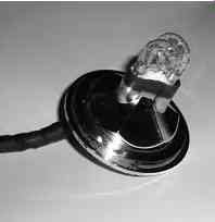
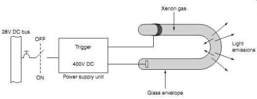
FIG. 1 Strobe/xenon gas tube schematic
FIG. 2 Strobe/xenon gas tube product
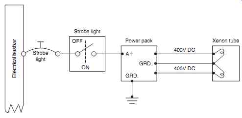
FIG. 3 Strobe/xenon gas tube circuit
FIG. 3 illustrates a typical strobe light circuit; this comprises a low-voltage power supply and a 400V DC power pack that provides a dual power sup ply. Shielded cables are required between the power pack and strobes to minimize the effect of electro magnetic interference (EMI). A high-energy pulse of current is triggered through the ionized gas on a cyclic basis. The ionization decreases the electrical resistance of the gas such that a pulse in the order of thousands of amperes is conducted through the gas.
When this current pulse travels through the tube, it imparts energy into the electrons surrounding the xenon atoms causing them to move up to higher energy levels. The electrons immediately drop back into to lower energy levels, thereby producing pho tons. Strobes are a source of short-wavelength ultra violet radiation together with intense emissions in the near infrared; the overall effect is a high-intensity white flash.
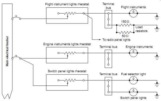
FIG. 4 Rheostat light intensity control
Key maintenance point
400 V DC used in strobe circuits is dangerous: take all necessary health and safety precautions when working near the system.
Key maintenance point
Do not handle strobe tubes with bare hands; moisture causes local hot-spots that can lead to premature failure.
Test your understanding
Briefly explain the difference between the following lighting technologies:
-- incandescent
-- light-emitting diode (LED)
-- electro-luminescent
-- fluorescent
-- strobe.
2. Flight compartment lights
Lighting is needed for the illumination of instruments, switches and panels. Dome lights located on the ceiling provide non-directional distribution of light in the compartment; it typically contains an incandescent lamp and is powered from the battery or ground services bus. Flood lighting in the flight compartment from incandescent lamps and/or fluorescent tubes pro vides a general illumination of instruments, panels, pedestals etc. Fluorescent tubes located beneath the glareshield provide overall illumination of the instrument panels. Emergency lights are installed in the
flight compartment for escape purposes. The color of flight compartment lights is normally white; this reduces the power and heat, improves contrast on the instruments, and reduces eye fatigue.
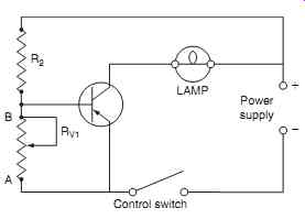
FIG. 5 Transistor lighting control circuit
2.1 Instruments
Internal instrument lighting is normally from incandescent lamps integrated within individual instruments; lighting must be shielded from causing any direct glare to the pilot and must be dimmable.
External instrument lighting is provided by pillar (or bridge) lights positioned on the panels for individual instruments. The light intensity can be dimmed by a simple rheostat device as illustrated in FIG. 4; this typical circuit is for flight instruments, engine instruments and switch panels.
The increased quantity of instruments requires electronic control in place of rheostat due to the higher loads. A transistor circuit provides electronic control as illustrated in FIG. 5 ; variable resistor R V1 varies the (relatively low) base current into the base of a PNP transistor; this controls the (relatively high) current through the collector and lamp. A typical transistor controlled lighting system is illustrated FIG. 6. The relatively low base currents in the respective transistors can now control a variety of lighting circuits:
-- radio navigation systems
-- compass
-- fuel panels
-- engine indications
Instrument panels are often constructed from Perspex; the surface is painted and then engraved with the identification of switches and controls; the panel is illuminated from the edges. The light is dispersed through the panel, but is only seen through the engravings. Alternatively, electro-luminescent panels are used; these are AC powered and energy efficient. Referring to FIG. 7, the phosphorus layer is laminated between front and rear clear plastic layers. The phosphorus material glows when AC power is applied; the front of the panel is painted to match the color of other panels. Engraved lettering or symbols remain clear and transmit light from the glowing phosphorus layer.
2.2 Master warning
An increasing number of systems are being designed into aircraft; this leads to more warning lights and larger panels with an increased possibility of a warning light being missed by the crew. This has led to centralized ' attention getters ', or master warning and caution light panels, a typical arrangement is shown in FIG. 8. The lights are located within pilot's immediate view, typically on the glareshield. Master caution and warning systems were developed to ease pilot workload, particularly on aircraft designed for operation without a flight engineer. In addition to the attention getter, it also directs the pilot towards the problem area concerned. The system annunciators are usually arranged such that the cautions are in the same orientation as the main system panels, e.g. the overhead panel.
A simplified master warning circuit is illustrated in FIG. 9. In this example, switch contacts 1 and 2 represent the individual warning signals from two different systems. In the event of a failure or malfunction, closure of either switch causes its corresponding warning light to illuminate together with the master warning (MW) light. The master warning and caution light is cancelled by pressing the light caption, whilst the crew react and investigate the reason for the warning. Typical panels could have up to 50 individual warning lights, any one of which also illuminates the master warning light. The individual lights could be located on an overhead or side panel.
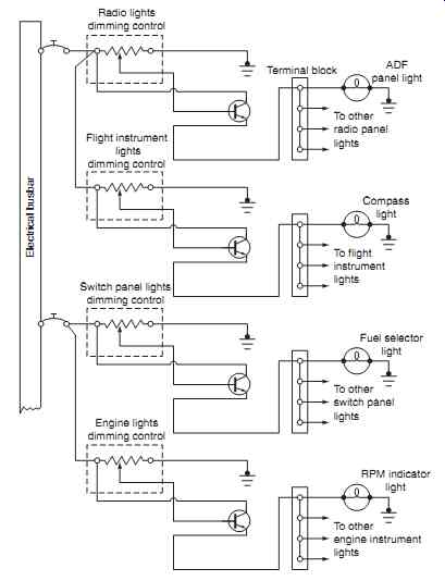
FIG. 6 Transistor lighting control system
=======
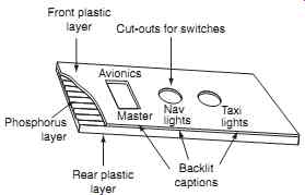
FIG. 7 Phosphorus lighting panel
Cut-outs for switches; Backlit captions; Rear plastic layer; Front plastic layer; Phosphorus layer; Avionics; Master Nav lights; Taxi lights
=======
Key point
A diode is required in the warning light circuit to ensure that only the relevant system light is illuminated.
When the master warning or caution light is illuminated, the pilot cross-refers to a centralized group of warning lights on the relevant panel, each connected to the warning devices of specific systems. The individual systems are identified by the system name and are located within the pilot's scan. Warning lights can be tested by a separate test switch, or by a centralized master dim and test switch. The night/day switch is used to reduce the intensity of warning lights during low ambient lighting conditions. Referring to FIG. 10(a), warning and caution lights affecting system operation and aircraft safety are defined by specific colors:
-- warning, red, an unsafe condition exists
-- caution, amber, an abnormal condition exists, but it is not unsafe
-- advisory, green or blue, a safe condition exists, or for information e.g. gear down.
Some installations have a comprehensive master warning and caution light panel that occupies the entire upper instrument panel, see FIG. 10b
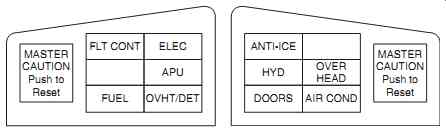
FIG. 8 Master warning and caution lights
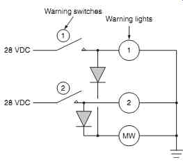
FIG. 9 Simplified master warning circuit
2.3 Emerging technology
Digital technology is replacing traditional wire bundles from the flight compartment to the equipment bays. A digital processor on each warning and caution module replaces lighted switches with the associated wire bundles. LEDs can now provide sufficient brightness to replace incandescent lighting with 30% power reduction compared with fluorescent lighting. The objectives are to accomplish weight, cost and reliability goals while giving flight crews what they are used to seeing in older flight compartments, including the tactile feel for push buttons and controls for lighting and dimming.
Key point: Lights used for certain warnings are not dimmable, e.g. fire and overheat. This is to ensure that the warnings are not missed under bright ambient lighting conditions.
3. Passenger cabin lights
Interior lighting installations for the passenger cabin vary depending on the size of aircraft; this ranges from a small quantity of roof-mounted incandescent lamps, through to integrated lighting concealed within the interior trim. These lights are controlled from the flight attendants ' station. LED illumination is being specified on business and passenger aircraft that have pre-programmed settings for specific flight phases and time zones. The systems are automatically controlled to customize the mixing of colors and lighting levels; this is intended to help passengers combat the fatigue of long-distance travel.
Traditionally, each cabin light is controlled individually; this technology is being replaced by a central control unit connected to all the lights in the cabin. Those lights are linked via a data bus to their respective control units; each of the lights can be programmed for different scenarios.
Implemented through software, the lighting in the cabin is a mixed array of colors. LED technology offers higher reliability and reduced maintenance costs compared to incandescent and fluorescent lights.
Cabin signs, e.g. 'return to seat' or 'no-smoking', are normally activated by the flight crew; on some aircraft the lights are armed by the crew and then activated automatically. Passenger reading lights are controlled from individual seat controls.
=======
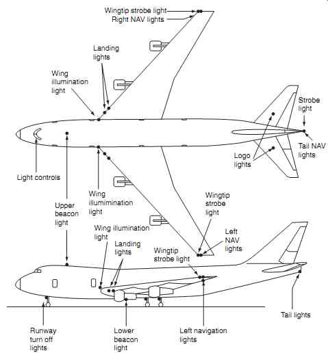
FIG. 11 Exterior lights (large transport aircraft)
Runway turn off lights Lower beacon light Left navigation lights Wingtip strobe light Left NAV lights Wingtip strobe light Landing lights Wing illumination light Upper beacon light Wing illumination light Logo lights Tail NAV lights Strobe light Landing lights Right NAV lights Wingtip strobe light Wing illumination light; Light controls; Tail lights
========
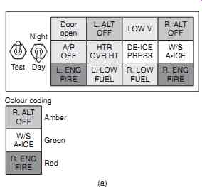
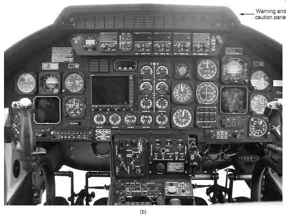
FIG. 10 Warning and caution panels: (a) typical arrangement, (b) helicopter
installation
Additional entry floodlights are provided in the door areas. Exit lights are located adjacent to the emergency exits and are clearly visible, irrespective of whether the door is open or closed. Floor path lighting is used to in emergency situations to provide visual identification of escape routes along cabin aisle floor. These systems have sufficient energy to enable passengers to identify aisle boundaries. The system guides the passengers to designated emergency exits in accordance with the specific certification requirements of the aircraft.
4. Exterior lights
An overview of the exterior lighting arrangement on a large passenger aircraft is illustrated in FIG. 11. Exterior lighting is used for:
-- logo illumination
-- landing/taxiing
-- wing illumination
-- anti-collision/navigation.
========
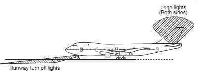
FIG. 12 Exterior lights (turn off/logo)
Logo lights (Both sides)
Runway turn off lights
========
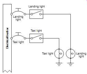
FIG. 13 Fixed landing light circuit
Landing light Landing light Landing light Taxi light Taxi light Taxi light
Electrical busbar
========
4.1 Logo lights
Referring to FIG. 12, logo lights are used to illuminate the tail fin; this is primarily for promotional purposes, i.e. for the airline to highlight their logo during night operations at an airport. Apart from the advertising value at airports, they are often used for additional awareness in busy airspace. Taxi lights (or runway turn off lights) are sealed beam devices with 250 W filament lamps located on the nose, landing gear or wing roots. They are sometimes combined with the landing light and used when approaching or leaving the runway. Taxi lights improve visibility during ground operations; they are directed at higher angle than landing lights. Runway turnoff lights, in the wing roots, are normally only used at night on poorly lit runways. A typical fixed landing and taxi light circuit is shown in FIG. On some aircraft types, taxi lights will switch off automatically with gear retraction. It is common practice to have taxi lights on whilst the aircraft is in motion as a warning to other aircraft and vehicles.
4.2 Landing lights
Landing lights are located on the wing tips, or on the front of the fuselage, usually at fixed angles to illuminate the runway. They are sealed beam devices with 600-1000 W filament lamps; a parabolic reflector concentrates light into a directional beam. The high current requirement is controlled via a relay.
Some landing light installations have a retractable assembly located on the underside of the wing. This has a reversible motor and gear mechanism to drive the light out against the airflow; a typical circuit . The alternative location for a landing light is in the wing leading edge; this has a transparent cover to provide aerodynamic fairing.
Inboard and outboard landing lights ( FIG. 15) pro vide extended illumination of the landing area.
4.3 Wing illumination
Ice inspection lights ( FIG. 15) are often installed to check ice formation on wing leading edges and engine intakes. Typical lights are the sealed beam type with filament lamps of 50-250 watts. They are recessed into the fuselage or engine nacelle with a preset direction that illuminates a section of the wing that can be viewed from the flight compartment. (More details on ice detection are given in Section 15.)
=======
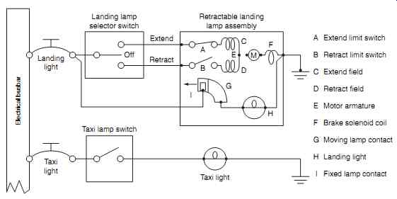
FIG. 14 Retractable landing/taxi light circuit
A Extend limit switch B Retract limit switch C Extend field D Retract field E Motor armature F Brake solenoid coil G Moving lamp contact H Landing light
I Fixed lamp contact
=======
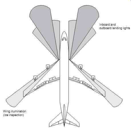
FIG. 15 Exterior lights (landing/wing)
Inboard and outboard landing lights Wing illumination
(Ice inspection)
=======
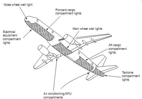
FIG. 16 Exterior lights (servicing)
Air conditioning/APU compartments Tailcone compartment lights Aft cargo compartment lights Main wheel well lights Forward cargo compartment lights Nose wheel well light Electrical equipment compartment
lights
===========
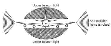
FIG. 17 Exterior lights (beacons/strobes)
Lower beacon light Anti-collision lights (strobes)
Upper beacon light
========
4.4 Service lights
Service lights are provided throughout the aircraft as illustrated in FIG. These lights are powered from the aircraft ground servicing bus. Examples include:
-- cargo bays
-- wheel wells
-- equipment bays
-- fuelling panels
Wheel wells lights are normally only used during the turnaround at night during the pre-flight inspection; they can also be used on to see the mechanical gear down-lock indications at night.
4.5 Navigation lights
The primary external lights required for navigation purposes are the beacons and anti-collision lights, see FIG.
4.5.1 Navigation lights
The navigation (or position) lights are a legal requirement for night flying. Navigation lights are normally based on filament lamps, providing steady illumination. They are located at the extremes of the aircraft, see FIG. 18, and provide an indication of the air craft's direction and maneuvers. Navigation lights are based on regulations that define the color, location and beam divergence such that the aircraft is visible from any viewing angle; these colors and divergence angles are:
-- green, starboard wing, divergence of 110 degrees
-- red, port wing, divergence of 110 degrees
-- clear (white), tail, divergence of ± 70 degrees either side of aircraft centerline (140 degrees total)
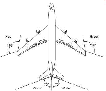
FIG. 18 Navigation lights - angular coverage
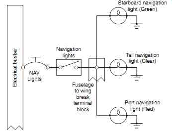
FIG. 19 Navigation light circuit
The traditional location of the white light is on the tail cone or fin tip; some aircraft have the rear facing light on the trailing edge of each wing tip. The wing lamps are 20 W filament lamps, the tail lamp is 10 W. Colored filters produce the specific colors; these filters must not shrink, fade or become opaque. A typical navigation light circuit is shown in FIG. Note that the lights are controlled by single switch and protection device.
Some aircraft are installed with LED position lights; these are formed with a bank of LEDs, see FIG. Helicopters have varying navigation light installations due to their specific geometry, see FIG. 21.
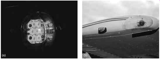
FIG. 20 Position lights: (a) LED type; (b) wing tip location
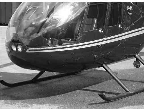
FIG. 21 Helicopter lights: Twin landing lights on nose; Navigation light
below door; Additional landing light on rear skid
======
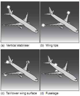
FIG. 22 Anti-collision strobe lights
(a) Vertical stabilizer (b) Wing tips
(c) Tail/lower wing surface (d) Fuselage
======
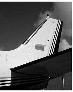
FIG. 23 Rotating beacon (top of fin)
4.5.2 Anti-collision lights
Anti-collision lights often supplement navigation lights; these can be provided either by a strobe light, rotating beacon or a combination of both, see FIG. 22. Anti-collision lights are also used as a warning that the engines are running or are about to be started. They are typically not switched off until it is considered safe for ground personnel to approach the aircraft. Strobe lights are typically located on the:
-- vertical stabilizer
-- wing tips
-- tail/lower wing surfaces
-- fuselage
These anti-collision lights are controlled by a single switch, with a single protection device. Anti-collision lights used in conjunction with the navigation lights enhance situational awareness for pilots in nearby air craft, especially during night-time or in low-visibility conditions.
The rotating beacon comprises a filament lamp, reflector, motor and drive mechanism that gives the effect of a light through a red filter that flashes 40-50 times per second. A typical rotating beacon is illustrated in FIG. 23. They are located on tail fins and the upper and lower fuselage (or tail boom on a helicopter).
Strobe lights are wing-tip and tail-fin mounted to supplement navigation lights. The strobe light produces a high intensity white flash of 1 mS duration at approximately 70 flashes per minute through a white or red filter; these provide light that can be seen from several miles.
Many external lights are based on sealed beams. A sealed beam combines an incandescent filament lamp and reflector into a single assembly. The reflector concentrates the light from the lamp into a predetermined beam shape; the assembly is fitted with a clear glass front cover that is permanently sealed to the reflector and cannot be removed. The filament lamp is inserted through a hole in the rear of the reflector and retained by a locking mechanism.
5. QUIZ--Multiple choice questions
1. A high-intensity white flash is produced from a:
(a) strobe light
(b) fluorescent tube
(c) landing light.
2. A clear (white) light with a divergence of ± 70 degrees either side of aircraft centerline is the:
(a) landing light
(b) rear position light
(c) logo light
3. Incandescence is the radiation of light from:
(a) a gas-discharge device
(b) an electrical filament due to an increase in its temperature
(c) a combined optical and electrical phenomenon.
4. Anti-collision lights can be provided by:
(a) rotating beacon or strobe lights
(b) fluorescent tubes
(c) retractable assembly.
5. Green or blue lights in the instrument panel indicate:
(a) a safe condition exists
(b) an unsafe condition exists
(c) an abnormal condition exists.
6. Flood lighting in the flight compartment is normally from:
(a) strobe lights
(b) incandescent lamps and/or fluorescent tubes
(c) position lights.
7. Sealed quartz or glass tubes filled with xenon gas are called:
(a) fluorescent tubes
(b) LEDs
(c) strobe light
8. The starboard wing tip navigation light has the following color and divergence:
(a) red and 110 degrees
(b) green and 110 degrees
(c) white and _ 70 degrees.
9. Anti-collision lights are used in conjunction with the:
(a) master warning lights
(b) wing inspection lights
(c) navigation lights.
10. Red warning lights in the instrument panel indicate the existence of:
(a) unsafe conditions
(b) abnormal conditions
(c) safe conditions.
11. Referring to FIG. 24, this device is a:
(a) strobe/xenon tube
(b) fluorescent tube
(c) LED
12. Referring to Fig. 25, the diode is required to:
(a) provide dimming
(b) ensure the correct light is illuminated
(c) ensure both lights are illuminated.
13. Referring to Fig. 26, this illustrates the angular coverage for:
(a) wing illumination lights
(b) rotating beacons
(c) navigation (or position) lights.
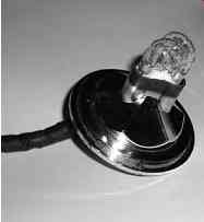
FIG. 24 See Question 11
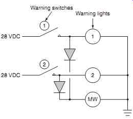
FIG. 25 See Question 12
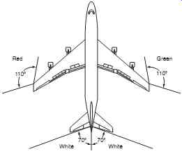
FIG. 26 See Question 13
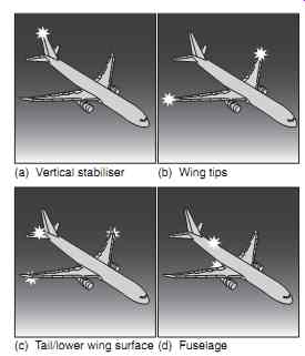
FIG. 27 See Question 14
(a) Vertical stabilizer (b) Wing tips
(c) Tail/lower wing surface (d) Fuselage
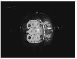
FIG. 28 See Question 16
15. Master caution and warning lights are located on the:
(a) lower instrument panel
(b) upper instrument panel
(c) overhead panel
16. Referring to Fig. 28, this light assembles comprises:
(a) LEDs
(b) strobes
(c) incandescent elements