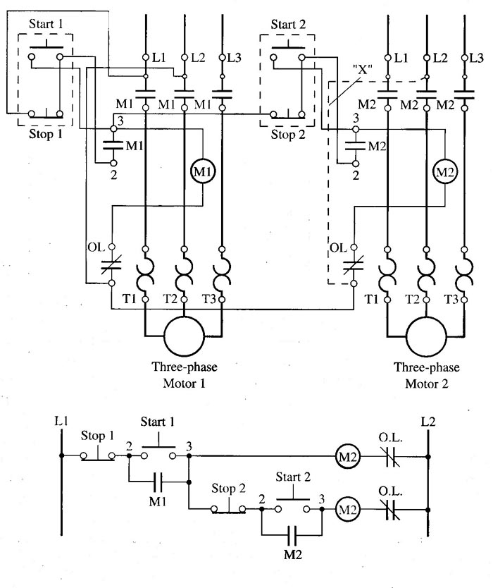
Sequence control allows a motor starter to be utilized as part of a complex motor control circuit that uses one set of conditions to determine the operation of another circuit. Figure 1 shows an example of this type of circuit. The circuits in this figure are presented in wiring diagram and ladder diagram form. One may really begin to see the importance of the ladder diagram as it shows the sequence of operation, which would be difficult to determine from the wiring diagram. The wiring diagram is still important since it shows the field wiring connections and the locations of all terminals that will need to be used during troubleshooting.
The operation of the circuit in Figure 1 shows two conveyors that are con trolled by two separate motor starters. Conveyor 1 must be operating prior to conveyor 2 being started. This is required because conveyor 2 feeds material onto conveyor 1 and material would back up on conveyor 2 if conveyor 1 was not operating and carrying it away. The ladder diagram shows a typical start/stop circuit with an auxiliary contact being used as a seal around the start button. When the first start button is depressed, Ml will be energized, which will start the first conveyor in operation. Mi auxiliary contacts will seal the start button and provide the circuit power to the second start/stop circuit.

Above: Fig. 1: (Click here for full-sized
image) Motor starters are sequenced
so that motor starter 1 must be on be fore motor starter 2 is started.
Since the second circuit has power at all times after M1 is energized, its start and stop buttons can be operated at anytime to turn the second conveyor on and off as often as required without bothering the first conveyor motor starter. Remember: This circuit requires conveyor 1 to be operating prior to conveyor 2, since conveyor 2 feeds material onto conveyor 1.
The circuit also protects the sequence if conveyor 1 is stopped for any reason. When it's stopped, the M1 motor starter becomes de-energized, and the M1 auxiliary contacts return to their open condition, which also de-energizes power to the second conveyor’s start/stop circuit.
Notice that the power for this control circuit comes from the L1 and L2 of the first motor starter. That is, if supply voltage for the first conveyor motor is lost for any reason, such as a blown fuse or opened disconnect, the power to the control circuit is also lost and both motor starters will be deenergized, which will stop both conveyors. If the first motor draws too much current and trips its overloads, it will cause an open in the motor starter’s coil circuit, which will cause the auxiliary contacts of the first motor starter to open and de-energize both motor starters.
If you need additional confirmation that the belt on the first conveyor is actually moving, a motion switch can be installed on the conveyor, and its contacts would be connected in series between the first start button and Mi coil. This would cause the first motor starter coil to become dc-energized.

