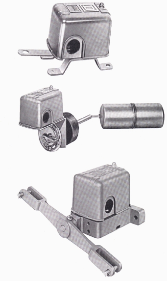
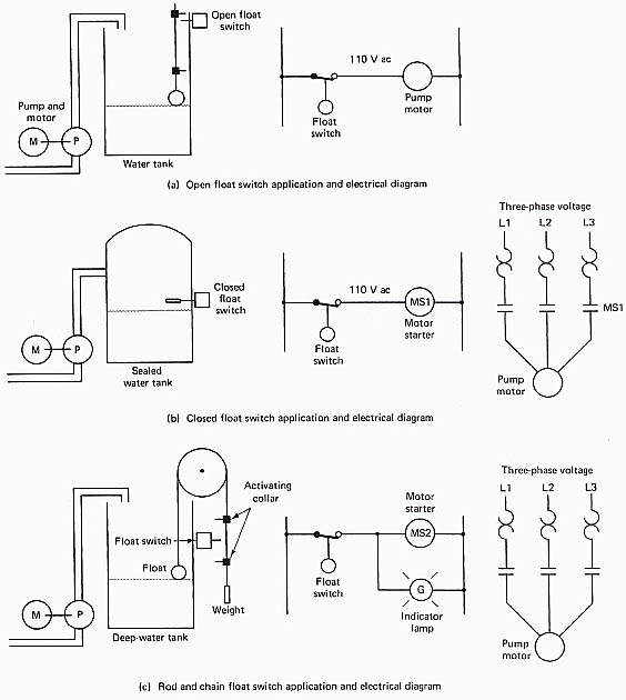
A wide variety of other pilot devices is commonly used in motor control circuits that are interfaced to industrial electronic circuits. These switches include pressure, level, and temperature switches as well as other types of switches. Figure 1 shows pictures of three types of level switches and Figure 2 shows example diagrams of each of these switches. The level switches are sometimes called float switches.

Above: Fig. 1 Three types of level switches. Applications and electrical
diagrams of these switches are shown in the next figure.

Above: Fig. 2 (a) A float and rod are used with the level switch
to turn it on and off. (b) A closed flow switch is mounted at the specific
level that is controlled. (c) A float is attached to one end of a cable and a weight is attached to the other end. When the float moves up or
down, the switch is activated.
The first switch in Figure 2a is used with a ball float that is attached to a long rod. The rod has adjustable cams attached at the bottom and the top of the rod. When the level in the sump raises, the float will lift the rod, and the cam that is attached to the lower part of the rod will move high enough to trip the switch handle to the up position, which closes the level switch contacts. When the pump runs, it will pump the sump level down and allow the float to drop. When the float drops low enough, the cam that is attached to the top of the rod will cause the switch handle to move to the down position, which will turn the pump off.
The switch in Figure 2b uses a sealed float to activate the level switch. In this application, the switch is mounted in the tank at the precise level. When the level of the liquid in the tank increases above this level, the float will lift and cause the switch contacts to close and turn on the pump. When the pump runs, the level of the tank is decreased, which allows the float to drop and turn the switch off. It's important to understand that the length of the switch arm will determine the amount of travel the float must make to turn the switch on and off. This distance is called the control band or dead band.
The float switch in Figure 2c shows a pivot-arm level switch. An arm or a wheel can be attached to the pivot to cause it to activate. An arm is shown in the picture of this switch, and a wheel is shown in the diagram. A cable is threaded around the wheel or arm. A float is attached to one end of the cable and a weight is attached to the other. When the level of liquid in the tank changes, the cable will move up or down and cause the switch to turn on or off.
It's important to understand that since these switches are pilot switches, they can only safely switch 10-15 A. That is, they can be used to control small motors, or they can control larger motors by switching power on and off to a motor starter coil.
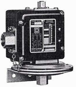
Another type of pilot switch is a pressure switch, which is used for sensing air pressure or water pressure and turning a set of contacts on or off. Figure 3 shows a typical pressure switch. The pressure switch may have a single point where it's activated, or it may provide a span between the point where it turns on and off. If the switch has a span adjustment and a low-pressure adjustment, one should set the low-pressure adjustment where one wants the switch to turn on, and adjust the span to determine where one wants the switch to turn off. For instance, if one wants the switch to control the pressure in a reservoir of an air compressor, one would set the low pressure to turn on when the pressure reaches 20 psi, and then set the span to 40 psi. The span of 40 psi would cause the switch to turn off when the air pressure reaches 40 psi more than the low-level setting. That is, the switch would turn on the compressor when the air pressure dropped to 20 psi, and it would turn the compressor off when the pressure reached 60 psi. Even though the switch has two points that turn it on and off, it will still only have one set of single-pole or double-pole contacts that is activated.

Above: Fig. 3 Example of a typical pressure switch that is used
as a pilot device.

