The drum switch is a manual switch that lets one manually reverse the direction in which a motor is turning. The switch contacts are open and closed manually by moving the drum switch from the off position to the forward or reverse position. Figure 1 shows a picture of the drum switch and Figure 2 shows a diagram of the drum switch contacts. Figure 2a shows the drum switch contacts when the switch is in the reverse position, Figure 2b shows the contacts when the switch is in the off position, and Figure 2c shows the contacts when the switch is in the forward position. When the switch is in the reverse position, note that terminal 1 is connected to terminal 2, terminal 3 is connected to terminal 4, and terminal 5 is connected to terminal 6. In the off position, all contacts are isolated from all other contacts. In the forward position, terminal 1 is connected to terminal 3, terminal 2 is connected to terminal 4, and terminal 5 is connected to terminal 6.
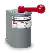
Above: Fig. 1: A drum switch. Notice the handle requires
the operator to manually change the position of the switch from forward
to reverse or to the off position.
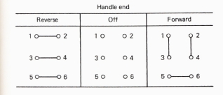
Above: Fig. 2: (a) Contacts of a drum switch when it's switched to
the reverse position. (b) Contacts of a drum switch when it's switched
to the off position. (c) Contacts of a drum switch when it's switched to
the forward position.
After understanding the operation of the drum switch in its three positions and the methods of reversing each type of motor, these concepts can be combined to develop manual reversing circuits for any motor in the factory as long as its full- load and locked-rotor amperage (FLA and LRA) don't exceed the rating of the drum switch. Figure 3a shows an AC single-phase motor connected to a drum switch. Notice that the start winding must be reversed for the motor to run in the reverse direction, so the start winding is connected to terminals 3 and 2.
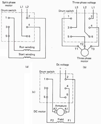
Above: Fig. 3: (a) A single-phase AC motor connected to a drum switch.
(b) A three-phase AC motor connected to a drum switch. (c) A DC motor connected
to a drum switch.
Figure 3b shows a three-phase motor connected to a drum switch. Realize that with this switch, any two lines to the motor can be swapped so the motor will change direction of rotation. Figure 3c shows a DC motor connected to a drum switch. Note with the DC motor that the direction of current flow through the field is reversed to make the motor run in the opposite direction. If you're a technician, you may need to study the connections inside the drum switch when it's in the forward or reverse position to fully understand how the drum switch is used with each of these motors to reverse the direction of their rotation.
These diagrams are especially useful for installation and troubleshooting of these circuits. The drum switch can be tested by itself or as part of the reversing circuit. The motors can also be disconnected from the drum switch and operated in the forward and reverse directions for testing or troubleshooting if you suspect the switch or motor of malfunctioning.

