 DC and AC motors can be reversed with respect to rotation This may be done
via terminal connections for each type of DC motor, AC single-phase motor, and AC three-phase motor. The circuit shown in Figure 1, right, (click
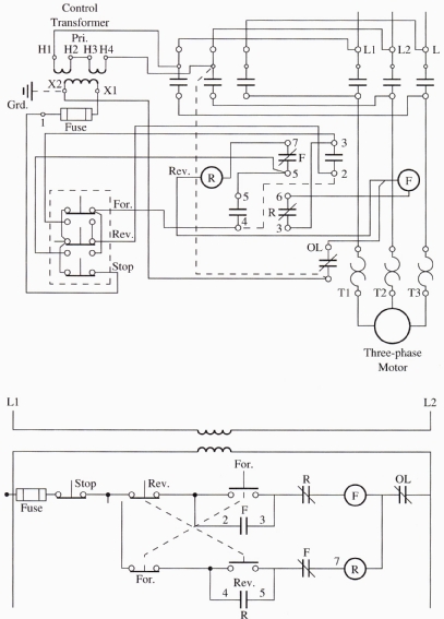
here for full-sized diagram) shows a forward and reverse motor starter
for an AC three-phase motor. If you must install or troubleshoot this circuit,
be sure to provide interlocks so that the motor can't be energized in
both the forward and reverse directions at the same time.
DC and AC motors can be reversed with respect to rotation This may be done
via terminal connections for each type of DC motor, AC single-phase motor, and AC three-phase motor. The circuit shown in Figure 1, right, (click
here for full-sized diagram) shows a forward and reverse motor starter
for an AC three-phase motor. If you must install or troubleshoot this circuit,
be sure to provide interlocks so that the motor can't be energized in
both the forward and reverse directions at the same time.
Right: Figure 1: A wiring diagram and ladder diagram of a forward and reverse motor starter. Notice that one can clearly see the interlock system in the ladder diagram.
From this diagram, note that the control circuit has a forward and reverse push buttons. The forward and reverse push buttons both have NO and NC sets of contacts. In the ladder diagram each button switch shows a dashed line to indicate that both sets of contacts are activated by the same button. The forward and reverse push buttons are better defined in the wiring diagram, which shows that each switch has an open set and a closed set of contacts. The stop button is wired in series with the open contacts of both of these switches, so that the motor can be stopped when it's operating in either the forward or the reverse direction.
The operation of the push buttons is best understood through the use of a ladder diagram. The ladder diagram is used to show the sequence of the control circuit, while the wiring diagram shows the operation of the load circuit, which includes the motor and heaters for the overloads. The overload contacts are connected in the control circuit, where they will de-energize both the forward and reverse circuits if the motor is pulling too much current.
From the wiring diagram, also note that two separate motor starters are used in the circuit. The forward motor starter is shown on the right side of the reverse motor starter. Each starter has its own coil and auxiliary contacts that are used as interlocks. The location of the auxiliary contacts is shown in the wiring diagram, but their operation is difficult to determine there. Upon encountering the auxiliary contacts in the ladder diagram, their function can now be more clearly under stood.
This comparison of the ladder diagram and the wiring diagram should help one understand that one needs both diagrams to work on the equipment. The ladder diagram will be useful in determining what should be tested, and the wiring diagram is useful in showing where the contacts one wants to test are located.
Also note that the control circuit is powered from a control transformer that is connected across L1 and L2. The secondary side of the transformer is fused to protect the transformer from a short circuit that may occur in either coil.

