AMAZON multi-meters discounts AMAZON oscilloscope discounts
ills 9.9 and 9.10 show a typical computerized dc motor test bench. Everything except thermal tests should begin with a motor temperature of 25 +/-5 C. DC motor thermal tests determine safe operating area and thermal resistance values. Both tests determine the operating conditions for an 85 C winding temperature rise above room temperature by thermocouple or 90 C by resistance for Class B insulation.
For Class F insulation, the maximum temperatures increase to 110 and 115 C, respectively.
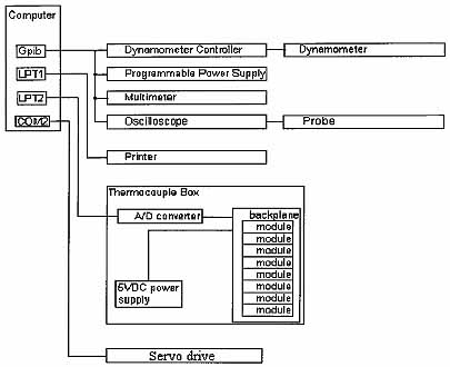
Ill. 9.9 Typical computerized dc motor test bench
diagram.
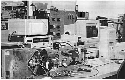
Ill. 9.10 Typical computerized dc motor test bench.
9.3.1 Voltage Constant Test
The Ke test checks the voltage constant in volts per thousand revolutions per minute (V/krpm) for a backdriven dc test motor. Any motor capable of maintaining an exact speed under a varying load can serve as a backdrive motor. For brush dc motors, measure the dc voltage generated by the test motor with a multimeter (generally in both rotations). For brushless dc motors, acquire the peak-to-peak voltage with an oscilloscope and divide by twice the drive speed in krpm to obtain the Ke.
9.3.2 Terminal Resistance Test
While multimeters can accurately measure brushless dc motor resistance, brush dc motors experience variations in brush contact drop as well as resistance changes based on the relative position of the brush to the commutator bars. Brush dc motors therefore require averaging several locked-rotor measurements to provide a stable reading, or, preferably, a dynamic measurement, while backdriven at low revolutions per minute. For either test, attach the motor terminals to a dc power supply and set the current limit high enough to reduce contact drop fluctuations and low enough to minimize heating during the test. In the absence of a specification, use a current limit of 25 percent of the rated motor current. Acquire the voltage necessary to drive the current through the motor for calculation of resistance (R = V/ I). For dynamic measurements, reverse either the polarity of the voltage or the rotation of the drive motor and average the two measurements to remove the counter-emf contribution.
Backdriven speeds of 30 to 100 rpm work reasonably well and will generally provide better repeatability than a locked test.
9.3.3 Speed-Torque Test
The speed-torque test provides a curve of the speed and the test motor torque (see ill. 9.11). Couple the shaft of the test motor to the dynamometer and attach the motor terminals to a programmable power supply. Set the supply voltage limit at the rated motor voltage and the current limit to the rated peak current. Acquire voltage and current from the programmable power supply and speed and torque from the dynamometer controller.
By using the dynamometer controller to take the motor from idle to a predetermined maximum torque and back to idle speed at a controlled rate, inertial effects will nearly disappear simply by interpolating for the same speed points and averaging the two sets of data. Points from the resulting curves will then compare very well with static measurements made at the same performance point. In most cases, a dc motor curve won't include the locked point, since a test at stall will often risk demagnetizing the motor and /or damaging the commutator.
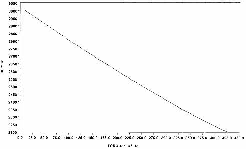
Ill. 9.11 DC motor speed-torque curve.
9.3.4 Demagnetization Test
The demagnetization test determines the amount of current the test motor can draw before reducing the Ke by 5 percent. Couple the shaft of the test motor to a dynamometer and attach the motor terminals to a dc power supply. Use an oscilloscope to monitor a current probe or current shunt on the positive output of the dc supply. Set the supply voltage limit to the rated motor voltage and the current limit well beyond the calculated demagnetization point. Using the oscilloscope to deter-mine the current, quickly apply torque until reaching the desired current. Remove all torque immediately and repeat two more times. Recheck the Ke of the test motor after allowing the motor to fully return to room temperature, generally after about 30 to 60 min. A reduction in Ke greater than 5 percent means the test motor has demagnetized. Otherwise, repeat the test at a higher current (typically in 5 percent increments).
9.3.5 Thermal Resistance Test
The thermal resistance test determines the temperature (deg. C) rise per watt loss of the test motor. Place the test motor into a stand and lock the shaft. For brush dc motors, route wires from the commutator and under the bearings to the outside for the winding resistance measurement, to avoid errors introduced by the brushes and the contact drop. Measure the cold winding resistance with the multimeter and record the ambient temperature. Attach a thermocouple to the shell to monitor the temperature rise. Attach the motor terminals to a programmable power supply. Slowly increase the voltage until reaching the rated current. Hold the rated current for 1 h after the shell temperature levels. Quickly detach the motor terminals and take the hot winding resistance with the multimeter. Record the ambient temperature.
Repeat the test for the rated running condition, preferably with a different motor for brush dc tests to avoid the possible effects of a burned commutator. The thermal resistance constant equals approximately:
![]()
Use a winding constant for copper of 0.00393.
where Rth is thermal resistance
Rhot is hot winding resistance
Rcold is cold winding resistance
amb cold cold ambient temperature
amb hot is hot ambient temperature
voltage hot is hot winding voltage
current hot is hot winding current
9.3.6 Safe Operating Area Curve Test
The safe operating area curve (SOAC) determines the boundaries of safe operation.
Use the running thermal resistance constant to estimate the winding temperature and maintain safe operating temperatures (usually below 85 C plus ambient). Place the test motor into a stand and couple the test motor to the dynamometer. Attach a thermocouple to the shell to monitor the temperature rise. Attach the motor terminals to a programmable power supply. Set the supply voltage limit at the rated motor voltage, and the current limit to the rated peak current. Start the current at the rated continuous motor current with the appropriate torque on the dynamometer. Adjust the voltage on the power supply to obtain the desired shell temperature when level.
Acquire the speed and torque from the dynamometer controller, and the voltage and current from the power supply. Adjust the torque as needed to keep the winding temperature at 85 C plus ambient. Repeat the test at the next desired level.
Acquire data at different speeds and torques to plot the SOAC. The winding temperature rise equals approximately:
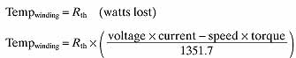
… where torque is in ounce-inches. Record the cold winding resistance at the beginning of the test, the hot resistance at the end of the test, and the ambient temperature for each measurement.
9.3.7 Holding Tests
The holding torque test determines the current, speed, and temperature at a specified torque. Place the test motor into a stand and couple the test motor to the dynamometer. Attach a thermocouple to the shell to monitor the temperature rise.
Attach the motor terminals to a programmable power supply. Set the voltage on the power supply to the rated motor voltage, the current to the rated continuous cur-rent, and the dynamometer to the desired torque. Run at the desired torque until the shell temperature levels. Acquire the speed and torque from the dynamometer controller, and the voltage and current from the power supply. Record the cold winding resistance at the beginning of the test, the hot resistance at the end of the test, and the ambient temperature for each measurement.
The holding speed test determines the current, torque, and temperature at a specified speed. The holding current test determines the speed, torque, and temperature at a specified current. The holding temperature test determines the speed, torque, and current at a specified temperature. The PC monitors the specific parameter and controls the test to hold it constant, similar to the holding torque test. The application determines which test will provide the most relevant data, and the PC automatically controls the test and acquires the data.
The PC then prints data sheets for all tests, prints summary sheets for SOAC and holding tests, and graphs for SOAC, speed-torque, and holding tests. For brushless dc testing, the servo drive takes the place of the programmable power supply. The volt-age divided by the current provides an estimate of resistance. During the SOAC test the PC uses the servo drive to control speed and the dynamometer controller to control torque to obtain the desired temperature.
9.3.8 Torque Ripple
The output torque of a dc motor at low speeds appears constant, but closer examination reveals a cyclic component called torque ripple, as illustrated in ill. 9.12. This torque ripple results from the switching action of the commutator, from the armature reluctance torque and sometimes from the bearings.
Torque ripple usually constitutes a very small percentage of the rated output torque and proves negligible for most uses. However, torque ripple may become critical in some applications, thereby requiring a means of measurement.
The apparatus illustrated in ill. 9.13 can accurately measure torque ripple, as long as the moment of inertia of the measuring device remains much smaller than the motor moment of inertia (otherwise inertia filtering invalidates the ripple measurement).
The percent peak-to-peak ripple torque equals:
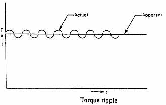
Ill. 9.12 Torque ripple test.
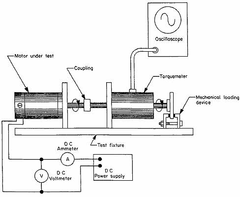
Ill. 9.13 Torque ripple test setup.