AMAZON multi-meters discounts AMAZON oscilloscope discounts
[cont. from part 3]
4.3 Coordination Modes and Setting Methods of Multistage Protection of Distribution Networks
This section takes the two kinds of protection coordination method described in Sections 4.1 and 4.2, and summarizes systematically the coordination mode, characteristics, and setting methods of multistage protection for distribution networks.
4.3.1 Coordination Mode of the Multistage Protection for Distribution Network
There are two kinds of coordination methods for multistage protection, one is the three-section over-current protection coordination method and the other is delay time differential coordination method. Four kinds of configuration modes can be derived from the differences between these two methods.
4.3.1.1 Mode 1: Coordination Mode with Single Three-Section Over-Current Protection
Stages possibly coordinated: N stage, the number N can be determined as in Section 1.
Required delay time differential: only one delay time differential is needed, ?t I
= 0 for section I protection and ?t II
= ?T for section II.
The minimum operation delay time of the substation outlet breaker: 0 s.
The longest operation delay time of the substation outlet breaker: ?T.
Advantages: it can achieve multistage protection coordination of the trunk line.
Disadvantages: the selectivity is poor and more users will suffer outage when a fault occurs.
For example, for the distribution network shown in Fig. 29(a), the outlet breaker S1 of a 10 kV substation and segment breakers A, (B, C), and D will constitute a four-stage three-section over-current protection, and B and C are both in the third stage. The time delays of Section I protection on the substation outlet breaker S1 and segment breakers of A, B, C, and D are all 0 s, while the time delay of section II protection is ?T.
4.3.1.2 Mode 2: Coordination Mode with Single Time Differential Protection
Stages possibly coordinated: generally, not more than three.
Required delay time differential: time delay instantaneous over-current protection should be adopted in the substation. For two-stage coordination, one time delay differential is needed, the delay time differential of the substation outlet breaker is
?t I = ?T, while the branch breaker is ?t 0
= 0. For three-stage coordination, a two stage time delay differential is needed, the delay time differential of the substation outlet breaker is ?t 2
= 2?T, while the branch breaker is ?t I
= ?T, the delay time differential of the sub-branch or user breaker is ?t0
= 0.
The minimum operation delay time of the substation outlet breaker: ?T for two-stage coordination and 2?T for three-stage coordination.
The longest operation delay time of the substation outlet breaker: ?T for two-stage coordination and 2?T for three-stage coordination.
Advantages: two-phase and three-phase short-circuit can coordinate fully, in which the branch fault does not influence the trunk line, and the sub-branch/user fault does not influence the branch. Fewer users will suffer power interruption.
Disadvantages: The substation must adopt time delay instantaneous over-current protection.
For example, for the distribution network shown in Fig. 29(b), the outlet breaker S1 of the 10 kV substation, branch breakers (A1, B1, B2, C1, D1, and D2), and sub branch breakers (A11, A12, C12, D21, and D22) will constitute the three-stage delay time differential protection coordination. The delay times of sub-branch breakers (A11, A12, C12, D21, and D22) are all 0 s, and the delay times of branch breakers (A1, B1, B2, C1, D1, and D2) are all ?T: the delay time of the outlet breaker S1 is 2?T.
4.3.1.3 Mode 3: Partial Coordination Mode with Single Time Differential Protection
Stages possibly coordinated: Generally there are two, when the feeder is long or the wire section is thin, three-stage coordination can also be achieved.
Required delay time differential: The instantaneous over-current protection and time delay instantaneous over-current protection should be adopted in the substation,
?t I
= 0 and ?t II
= ?T. The required delay time differential of the branch/sub-branch/ user switch is ?t0
= 0.
The minimum operation delay time of the substation outlet breaker: 0 s.
The longest operation delay time of the substation outlet breaker: ?T.
Advantages: Instantaneous over-current protection can be used in the substation, the branch fault does not influence the trunk line, and fewer users will suffer power interruption.
Disadvantages: When the feeder is short or the wire section is thick, the coordination can only be achieved in part of two-phase short circuit.
For example, for the distribution network shown in Fig. 29(c), when the two-phase short circuit fault occurs in downstream of the branch breaker (B2, C1, C2, D1, and D2), these branch breakers and the outlet breaker S1 of a 10 kV substation will constitute a two-stage delay time differential protection coordination, of which the delay time of the branch breaker (B2, C1, C2, D1, and D2) and the outlet breaker S1 of a 10 kV substation is 0 s.
4.3.1.4 Mode 4: The Mixed Coordination Mode of Three-Section Over-Current Protection and the Delay Time Differential Protection
The trunk line adopts the three-section over-current protection, but all the branch and sub-branch lines adopt delay time differential protection.
Stages possibly coordinated: n + 2 stages for a fully coordinated mode, and n + 1 stages for a partial coordination mode.
Required delay time differential:
1. When it is mixed with the two-stage fully coordinated delay time differential protection, the required delay time differential of section I of the substation outlet breaker and the trunk line breaker is ?t I = ?T, the required delay time differential of Section II of the substation outlet breaker and the trunk line breaker is ?t II = 2?T. The required delay time differential of the branch/sub-branch/users breaker is ?t0 = 0.
2. When it is mixed with the three-stage fully coordinated delay tine differential protection, the required delay time differential of section I of the substation outlet breaker and the trunk line switch is ?t I = 2?T, the required delay time differential of section II of the substation outlet breaker and the trunk line switch is ?t II = 3?T, ?t I
= ?T for the branch breaker, and ?t0
= 0 for the sub-branch/user breaker.
3. When it is mixed with partial coordination two-stage delay time differential, the required delay time differential of section I of the substation outlet breaker and the trunk line breaker ?t I
= 0, and the required delay time differential of section II of the substation outlet breaker and the trunk line breaker is ?t II
= ?T, the required delay time differential of branch/sub-branch/user breaker is ?t0 = 0.
The minimum operation delay time of the substation outlet breaker:
• The case mixed with the two-stage full coordination: ?T
• The case mixed with the three-stage full coordination: 2?T
• The case mixed with the two-stage partial coordination: 0.
The maximum operation delay time of the substation outlet breaker:
• The case mixed with the two-stage full coordination: 2?T
• The case mixed with the three-stage full coordination: 3?T
• The case mixed with the two-stage partial coordination: ?T.
Advantages: The selectivity is enhanced and fewer users will suffer a power interruption.
Disadvantages: When it is mixed with the full coordination, the protection rapidity of the substation outlet switch will decrease. When it is mixed with the partial coordination, the selectivity can be improved for a part of two-phase fault.
For example, for the distribution network shown in Fig. 29(d), the outlet breaker S1 of a 10 kV substation and segment switches A, B, and C will constitute four-stage three-section over-current protection coordination. The delay time of section I protection of the substation outlet breaker S1 and the segment breakers of A, B, and C is 2?T, and the delay time of section II protection of the substation outlet breaker S1 and the segment breakers of A, B, and C is 3?T. S1, A, B, C, branch breakers (A1, B1, C1, D1, and D2), and sub-branch breakers (A11, B21, D11, and D12) will constitute a three stage fully coordinated delay time differential protection. The delay time of sub-branch breakers (A11, B21, D11, and D12) is 0 s, and the delay time of branch breakers (A1, B1, C1, D1, and D2) is ?T. This example describes the mixed mode of the three- section over-current protection and the three-stage fully coordinated delay time differential protection.
As another example, for the distribution network shown in Fig. 29(e), the outlet breaker S1 of a 10 kV substation and segment switches A, B, and C will constitute four-stage three-section over-current protection coordination. The delay time of Section I protection of the substation outlet breaker S1 and segment breakers of A, B, and C is 0 s, and the delay time of section II protection of the substation outlet breaker S1 and segment breakers of A, B, and C is ?T. The delay time of branch breakers (B2, C1, D1, and D2) is 0 s. When a two-phase short circuit occurs downstream of branch breakers (B2, C1, D1, and D2), S1, A, B, C, and branch breakers (B2, C1, D1, and D2)
will constitute a two-stage partial coordinated delay time differential protection. This example describes the mixed mode of the three-section over-current protection and two-stage partial coordinated delay time differential protection.
4.3.2 Setting Principle of the Multistage Over-Current Protection in a Distribution Network
The setting principle of delay time of the coordinated multistage protection in a distribution network has been discussed in the previous sections; this section only discusses the setting principle of current of coordinated multistage protection in distribution network.
According to the "Setting guide for 3~110k V power system protection equipment" (DL/T584-2007), the current setting can be determined by the following principles.
It should be noted that the current setting only concerns with the line itself for a radial line. For a distribution network with multiple sources, the current setting needs comprehensive consideration in the case that the tie switch is closing and on one side the feeder powers additional loads transferred from the other source side. For example, for the hand-in-hand ring network, the determination of current setting should comprehensively consider both feeders and is at the condition of the switch closing.
Fig. 29 Typical coordination modes of multistage protection in distribution network
4.3.2.1 Setting Principle of Mode 1
Section I: The current settings under the three-phase short-circuit and the two-phase short-circuit should be calculated separately. The current setting under the three-phase short-circuit is set on the principle that the protection should not trip when the maximum three-phase short-circuit occurs at the end of this stage. The current setting of the additional stage protection is set with the principle that there is an enough sensitivity when a minimum three-phase short-circuit occurs at the end of this stage. The current setting under the two-phase short circuit is set on the principle that the protection should not trip when the maximum two-phase short-circuit occurs at the end of this stage. The current setting of the additional stage protection is set with the principle that there is enough sensitivity when a minimum two-phase short-circuit occurs at the end of this stage. The reliability coefficient of both sets of current setting should not be less than 1.3, while the sensitivity coefficient of both sets of current setting should not be less than 1.5.
Section II: The current settings under the three-phase short-circuit and the two-phase short-circuit should be calculated separately. The current setting under the three-phase short-circuit is set on the principle that its protection range should be smaller than that of the Section I protection on the next stage. The sensitivity should be checked with the minimum three-phase short-circuit current at the end of this stage. The current setting under the two-phase short-circuit is set on the principle that its protection range should be smaller than that of the Section I protection on the next stage. The sensitivity should be checked with the minimum two-phase short-circuit current at the end of this stage.
The reliability coefficient of both sets of current setting ranges from 1.1~1.2, while the sensitivity coefficient of both sets of current setting should not be less than 1.5.
The current setting of the last (but not the additional) stage can be set according to the requirement of ensuring sensitivity at the end of the line. Section II protection is not usually installed in the additional stage.
4.3.2.2 Setting Principle of Mode 2
The current setting of the substation outlet breaker can be determined as follows.
The current setting of the time delay instantaneous over-current protection is set on the principle that it is able to protect the whole length of the line, and there is enough sensitivity when a minimum two-phase short-circuit occurs at the end of the line. The sensitivity coefficient should not be less than 1.5.
The current setting of the branch/sub-branch/user breaker can be determined as follows. The current setting is set on the principle that the protection should not trip when the maximum load current and magnetizing inrush current from downstream unloaded transformer flows through the protection device. The reliability coefficient should not be less than 1.5.
4.3.2.3 Setting Principle of Mode 3
The current setting of the substation outlet breaker can be determined as follows.
Section I: The current setting is set on the principle that the protection should not trip when the maximum three-phase short-circuit occurs at the end of this stage. The reliability coefficient should not be less than 1.3.
Section II: The current setting is set on the principle that it is able to protect the whole length of the line and there is enough sensitivity when a two-phase fault occurs at the end of the line in the minimum operation mode of the system. The sensitivity coefficient should not be less than 1.5. For a radial line, the current set ting only concerts with the line itself. For a hand in hand ring network, the current setting concerts with the both feeders and should be at the condition of the tie switch closing.
The current setting of the branch/sub-branch/user breaker can be determined as follows. The current setting is set on the principle that the protection should not trip when the maximum load current and magnetizing inrush current from the downstream unloaded transformer flows through the protection device. The reliability coefficient should not be less than 1.5.
4.3.2.4 Setting Principle of Mode 4
1. N + 2 for full coordination The current setting of the trunk line breaker should be set on the principle as same as section I and section II in mode 1.
The current setting of the branch/sub-branch/user breaker should be set on the principle that the protection should not trip when the maximum load current and magnetizing inrush current from downstream unloaded transformer flows through the protection device. The reliability coefficient should not be less than 1.5.
2. N + 1 for partial coordination The current setting of the trunk line breaker can be determined as follows.
Section I: The current setting is set in the traditional way. That is to say, the cur rent setting is set on the principle that the protection should not trip when the maxi mum three-phase short-circuit occurs at the end of this stage. The current setting of the additional stage protection is set on the principle that there is an enough sensitivity when a minimum two-phase short-circuit occurs at the end of this stage. The reliability coefficient should not be less than 1.3, while the sensitivity coefficient should not be less than 1.5.
Section II: The current setting is set in the traditional way. That is to say, the cur rent setting is set on the principle that it is able to protect the whole length of this stage in any case but its protection range should be smaller than that of Section I protection on the next stage. The sensitivity should be checked with the minimum two-phase short-circuit current at the end of this stage. The reliability coefficient of both sets of current setting ranges from 1.1 to 1.2, while the sensitivity coefficient of both sets of current setting should not be less than 1.5.
The current setting of the last but not the additional stage is set to ensure enough sensitivity. Section II protection is not usually installed in the additional stage.
The current setting of the branch/sub-branch/user breaker should be set on the principle that the protection should not trip when the maximum load current and magnetizing inrush current from a downstream unloaded transformer flows through the protection device. The reliability coefficient should not be less than 1.5.
There are some other issues should be noted in the following.
1. For a radial branch, if an additional stage is added, the branch lines on the additional stage can't achieve partial coordination, due to the fact that Section I can protect the whole length of this stage and hence Section II protection is not installed. Therefore, the additional stage would be uninstalled if the trunk line of the additional stage is short and there are more branch lines.
2. For an interconnected distribution network, the current setting is concerned with the operation mode of the tie feeders.
4.3.2.5 Inrush Current Problem
The influence of magnetizing inrush current during the energizing of a distribution transformer on protection relay in a distribution network is enormous. Without considering the remanence, the closing inrush current of a distribution transformer can reach 5-8 times its rated current in the worst case. The inrush current can be even larger with the consideration of remanence. Generally, in the three-phase transformer with a phase difference of 120° in three-phase voltage, there is always one phase in the worst condition and the maximum magnetizing inrush current exists in this phase.
The closing inrush current that flows through the feeder switches is quite different from the magnetizing inrush current of a single transformer and it is a superimposition of the magnetizing inrush current of all distribution transformers downstream of this switch. When a fault occurs, a breaker with a protection device will trip to clear the fault and this action will lead to the power failure of each distribution transformer downstream of the breaker at the same time. Therefore, the remanence will be roughly of the same polarity. The closing afterwards (e.g., from a reclosure) will make each transformer energize again at the same time. Therefore, the amplitude of the closing inrush current that flows through this switch is a superimposition of the magnetizing inrush current of each distribution transformer.
For the distribution transformer, the inrush current is enormous at the closing moment.
However, the inrush current will decrease rapidly to a negligible range by 7-10 cycles (i.e., 0.14~0.2 s). Therefore, the closing inrush current has little effect on the section II protection (time delay instantaneous over-current protection) and section III protection (definite time over-current protection), but it has an enormous effect on section I protection (instantaneous over-current protection). If the current setting of section I protection is smaller than the inrush current, the closure to restore power service will not succeed due to the protection malfunction. For the case where the breaker configures a single shot reclosure, the inrush current is the main cause of the reclosing failure for an instantaneous fault. In this case, great attention will often be paid to seek the "permanent fault" that did not originally exist, and hence leads to a long-term power failure.
The main ways to solve the inrush current problem include:
1. Adopt a second harmonic restraint or detect the intermittent angle to distinguish the inrush current and the fault current, avoiding maloperation of section I protection.
2. Sacrifice the sensitivity of section I protection and increase the current setting to a larger value than the magnetizing inrush current. For the breaker with non-delay protection (such as section I) on the branch, due to a relatively small transformer capacity of downstream of the branch, the sympathetic inrush current that flows through the branch breaker is generally small, so it is possible to avoid the inrush current influence by sacrificing protection sensitivity.
3. Sacrifice the rapidity of section I protection by a time delay of 0.1~0.15 s. By this time, most of the inrush current has already decreased.
4. Restore the power service stage by stage: This measure can decrease the number of the distribution transformers that produces the sympathetic inrush current during every closing, thus decreasing the influence of the inrush current.
5. Cancel the delayed accelerated protection and add an appropriate time delay in reclosing control to decrease the influence of the inrush current.
4.3.2.6 Influence of DG
The influence of DG on the multistage coordination of time differential protection has been discussed in Section 4.1.3. This section mainly discussed the influence of DG on the multistage coordination of three-section over-current protection.
As mentioned, for the distribution network with DG, if a phase-to-phase short circuit occurs, the short-circuit current that flows through the substation outlet breaker and each segment switch along the feeder has changed compared to the case without a DG. Those changes need to be analyzed comprehensively when considering DG location on this feeder or the adjacent feeder from the same bus.
When the DG capacity is small and the DG is a converter type, the influence of it on the short-circuit current is generally small or negligible. The multistage configuration and the current setting principle of three-section over-current protection discussed in Section 4.3.3 can also be used.
When the DG capacity is enormous or the DG is a motor type, generally the influence on the short-circuit current cannot be ignored. The influence on the multistage configuration and the setting principle of three-section over-current protection discussed in Section 2.4.3.3 needs to be analyzed. The reverse protection can be canceled, but for forward protection, one of the following two measures should be adopted.
1. Adopt a more strict setting principle. It is necessary to appropriately increase the reliability coefficient and the sensitivity coefficient. First, determine the current set ting again without consideration of the DG, then check its reliability and sensitivity with the DG. The setting can be used if the check is passed.
2. If the reliability and sensitivity check is not passed, the coordination method of the auto-reclosing and grid-disconnected characteristics of photovoltaic generation should be adopted as follows:
a. The configuration of three-section over-current protection on the substation
outlet breaker is the same as described in Section 2.4.2, but a delay time of the single-shot auto-reclosure should be extended to 2~3 s.
b. The over current pulse counting function is set in the three-section over-current protection along the feeder and the starting threshold is set to one appearance of over-current or loss of voltage. That is to say, when the protection device experiences over-current for the first time, the three-section over-current protection is blocked. Only after the reclosing of the substation outlet breaker, will the second experience of over-current start up the three-section over-current protection.
With this configuration, when a fault occurs, the protection of the substation outlet breaker will trip (at this moment, the other switches along the feeder are maintained at the closing state), and all DGs will split from the grid within 2 s due to loss of voltage.
After a time delay more than 2~3 s, the substation outlet circuit breaker will be reclosed.
If the fault is temporary, the closing will succeed and the DG will return to the grid and restore to the normal state gradually. If the fault is permanent, the three-section over current protection of the corresponding breaker along the feeder will trip under protection coordination.
4.4 Example Analysis
Fig. 30 shows the 10 kV distribution network of a village. In this figure, the outlet line of the substation named X1 appears as a complex branch and is divided into two trunk lines. One is the No. 1 trunk line from the substation X1 to the tie switch N, its length is 11 km and uses the overhead line LGJ-240. Another is the No. 2 trunk line from X1 to the greenhouse Y for vegetable, its length is 27 km and uses overhead line LGJ-150. The No. 3 trunk line comes from the substation named X2 to the tie switch N, its length is 8 km and it also uses the overhead line of LGJ-240. The other lines are branch lines. Switches A-H are the segment breakers on the trunk lines. Switches Ai -Hi are branch or user breakers. It is assumed that the short-circuit capacity of the system in the maximum operation mode is 400 MVA and the short-circuit capacity of the system in the minimum operation mode is 260 MVA. The reliability coefficient Krel II
= 1.2 and Krel I
= 1.3, the sensitivity coefficient Ksen
= 1.5, and ß = 20%.
To fully illustrate the method discussed here, the protection relaying is configured in the following two situations.
4.4.1 Situation 1: Provided that the Current Protection on the Substation Outlet Breaker can be Delayed by a Time of ?T
According to the description in Section 4.3, it is appropriate to adopt the N + 2 full coordination mode in mode 4. The trunk line adopts three-section over-current protection, but the branch line adopts protection coordinated by the delay time differential.
For the trunk line 1 and the trunk line 3, because the two trunk lines contact each other via the tie switch, the configuration should be considered comprehensively at the condition of the tie switch closing (i.e., the load of one trunk line can be transferred to the other). The trunk line 1 can be configured with three-stage forward protection located in A, B, and C, respectively. The third protection can be extended to the trunk line 3 and an additional stage with reverse protection can be located at K. Trunk line 3 can be configured with three-stage forward protection located in I, J, and K, respectively. The third protection can be extended to the trunk line 1, and an additional stage with reverse protection can be located at L.
The trunk line 2 is a radial feeder and can be configured with five-stage three-section over-current protection located at D, E, F, G, and H; of these H is the additional stage of the protection.
It is known from the short-circuit calculation that the minimum three-phase short circuit current of each branch is 430 A and the minimum two-phase short-circuit current is 372 A. Therefore, the current setting of all the branch breakers can be set to 280 A for a three-phase fault and 240 A for a two-phase fault. The time delay is set to 0 s. Adopting the improved multistage protection coordination based on the differences of settings, the current setting of each stage protection on the three trunk lines is shown in the Table 2.4. In this table, the first set of setting values is used for the three-phase short-circuit and the second set of setting values is used for the two-phase short-circuit.
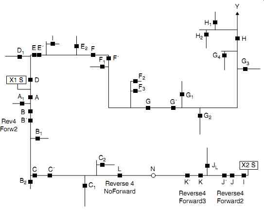
Fig. 30 A 10 kV distribution network of a village
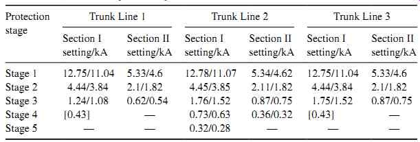
Table 4 Current settings of each protection on the trunk lines in situation
1
4.4.2 Situation 2: Provided that the Current Protection on the Substation Outlet Breaker can't be Delayed (Instantaneous Over-Current Protection)
According to the description in Section 4.3, it is appropriate to adopt the N + 1 partial coordination mode of mode 4. The trunk line adopts the three-section over-current protection, but the partial branch line adopts the protection coordinated by the delay time differential.
For trunk line 1 and trunk line 3, because the two trunk lines contact each other via the tie switch, the configuration should be considered comprehensively at the condition of the tie switch closing (i.e., the load of one trunk line can be transferred to the other). The trunk line 1 can be configured with three-stage forward protection located in A, B', and C', respectively. The third protection can be extended to the trunk line 3 and an additional stage with reverse protection can be located at J'. Trunk line 3 can be configured with three-stage forward protection located in I, J', and K', respectively.
The third protection can be extended to the trunk line 1 and an additional stage with reverse protection can be located at B'.
Trunk line 2 is a radial feeder and can be configured with four-stage forward three section over-current protection located at D, E', F', and G'; of these G' is the additional stage of the protection. The current setting of each stage protection on the three trunk lines can be set by the traditional methods of three-section over-current protection and the setting values are shown in Table 5.
It is known from the short-circuit calculation that the minimum two-phase short circuit current is 372 A. Therefore, the current setting of part of the branch breakers (A1 , B2 , J1 , D1 , E2 , F2 , F3 , G3 , and G4 ) can be set to 240 A and the time delay is set to 0 s.
Certainly, the current setting of each branch breaker can also be set with a different short-circuit current.
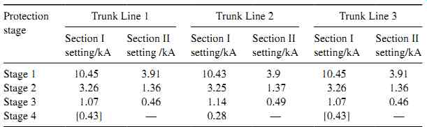
Table 5 Current settings of each protection on the trunk lines in situation
2
5. Summary
1. The distribution network with a grid-connected DG becomes an active network and the traditional protection method that was originally used for the single-ended source system is no longer suitable. The improved scheme and new protection method is proposed.
2. According to the situations where the DG is located in different places in the distribution network and with different configurations of reclosing, this Section proposes the corresponding adaptive improved strategies in the field of current protection configuration, ARDs, and DG. It is worth pointing out that wide-area differential protection technology based on the distribution intelligence control technology of a distribution automation system is the future developmental direction for active distribution networks.
3. For the substation outlet breaker that has not got instantaneous over-current protection installed, the three-stage differential protection coordination on the user (sub branch), branch, and substation outlet breakers can be realized. The fault in the branch cannot influence trunk lines and faults from users (sub-branch) cannot influence the branch either. The coordination of multistage protection relaying can improve the ability to clear faults in distribution automation systems.
4. Because most of phase-to-phase faults are two-phase faults, for the substation outlet breaker with instantaneous over-current protection, partial feeders still can coordinate by stage differential. So, coordination of protection relaying can improve the ability to clear a fault in the distribution automation system.
5. For the feeder uninstalling instantaneous over-current protection, the connection of DG will not affect the coordination of multistage differential protection in general.
For the feeder installing instantaneous over-current protection, if the DG is accessed to the adjacent feeder by the same bus, instantaneous over-current protection range of the substation outlet breaker will extend, but the coordination range of the multi stage differential protection will decrease. In order to avoid maloperation of the over-current protection due to a larger reverse fault current provided by the DG in this feeder, it is necessary to selectively configure the directional element.
6. For a distribution network with a long powering radius, the multistage three-section over-current protection coordination can be realized if there is a obvious difference in the short-circuit current along the line. The improved setting method based on the difference between the setting values of three- and two-phase faults can improve the sensitivity and protection range in a two-phase fault under the traditional setting method.
7. There are four-coordination modes, the coordination mode with single three- section over-current protection, the mode with single time differential protection, the partial coordination mode with simple delay time differential protection, and the mixed coordination mode with three-section over-current protection and the delay time differential protection, these modes are all derived from synthesizing the delay time differential and three-section over-current protection coordination methods. The characteristics of the four modes are analyzed, the configuration method and the setting principle of protection parameters are proposed.