AMAZON multi-meters discounts AMAZON oscilloscope discounts
[cont. from part 2]
4. Coordination of Multistage Protection in the Distribution Network
The distribution automation system collects fault information from the distribution automation terminals, locates and isolates the fault according to the fault location rules, and then reconstructs the network in order to restore power service of the non faulted area to the greatest extent. However, it will cause transient power interruption of the area in general, even if the fault only occurs in a radial branch.
Protection with coordinated relaying can clear a fault rapidly and restore the power supply to the non-faulted area without power interruption. However, the coordinated protection relaying in the distribution network is often difficult to achieve. On a practical level, the override and multiple stage trips usually happen due to the unreasonable configuration of multiple stage protection relaying and unreasonable parameter settings.
For the open-loop operating urban distribution network with short power supply radius but more segments, the short-circuit current in each segment switch makes little difference. Generally, only the cooperative scheme of protection relaying with pure delay time difference can be used to realize that the branch fault cleared will not influence trunk lines and the sub-branch fault cleared will not influence the branch.
However, by the delay time differential coordination, coordinating multistage protection relaying in the distribution trunk line cannot be achieved.
For the suburban or rural distribution network with a long power supply radius, there are obvious differences in the fault current in each segment switch when a fault occurs in the trunk line. At this time, it is feasible to adopt multistage coordination of three-section over-current protection.
This section discusses the possible coordination patterns, characteristics, and setting methods of multistage protection relaying in the distribution network.
4.1 Time Difference Based Coordination of Multistage Protection in the Distribution Network
For the open-loop operating mode of an urban distribution network with a short power supply radius but more segments, the short-circuit current only makes a little difference when the fault occurs in the different place. Hence, it is impossible to set different current setting values for different switches. At this time, the only way to clear the fault selectively is by the coordination of the delay time differential in multistage protections.
This section mainly discusses the multistage protection coordination based on the time differential, that is, the protection coordination is implemented by setting different delay times for the 10 kV outlet switch and 10 kV feeder switch in the transformer substation.
4.1.1 Feasibility Analysis
4.1.1.1 Case without Instantaneous Over-Current Protection
Instantaneous over-current protection can be uninstalled, but instead of time delay instantaneous over-current protection or definite-time over-current protection, in such cases where a line fault cannot cause bus voltage of power station or an important user getting lower than the 60% of rated voltage, the conductor section of the line is large enough to allow the fault to clear with a time delay, and the time limit of the over current protection is less than 0.5~0.7 s. The time delay instantaneous over-current protection or definite-time over-current protection makes the coordination of multistage differential protection possible.
4.1.1.2 Case with Instantaneous Over-Current Protection
A 10 kV feeder operating in the open-loop mode can be regarded as a single-ended source network, the current setting of instantaneous over-current protection (section I) I I.op
should be larger than the maximum three-phase short-circuit current at the end of the line,
 (18)
(18)
Where, Krel I
is the reliability coefficient and Krel I 13 . , Ik.max 3is the maximum three phase short-circuit current at the end of the line, which can be expressed as
 (19)
(19)
Where .
? E = equivalent potential of system source XS. min = equivalent reactance of the system source in the maximum operation mode
Z1 , Z2 , …, Zn = feeder impedance of each line segment from the head to the end of the feeder.
Assuming that feeders have the same conductor section, then:
 (20)
(20)
Where, l total is the total length of the feeder and z is the feeder impedance per unit length.
The main phase to phase fault that occurs in the overhead line distribution network is the two-phase short-circuit. Although most phase to phase faults in the cable can become three-phase faults gradually, the possibility of cable faults is very low. Faults, mostly two-phase faults, usually occur in the branch or user side of overhead line and the two-phase short-circuit current Ik 2 is 0.866 times the three-phase fault current.
The critical length l C on the feeder in the upstream of the fault point, at which the two-phase short-circuit in the maximum operation mode doesn't cause the operation of the instantaneous over-current protection, is
 (21)
(21)
And this formula can be rewritten as
 (22)
(22)
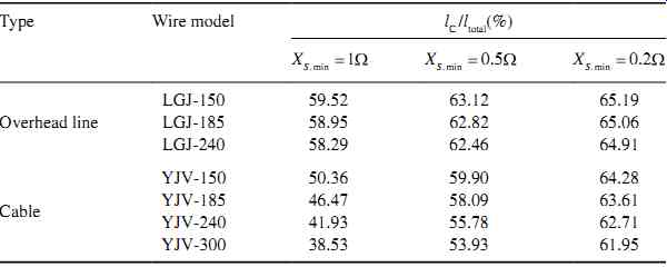
Table 1 The ratio of the critical length to the whole length of the feeder
(l = 10 km)
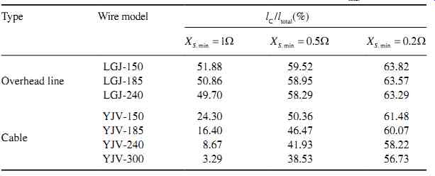
Table 2 The ratio of the critical length to the whole length of the feeder
(l = 5 km)
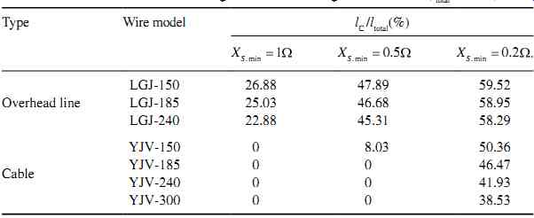
Table 3 The ratio of the critical length to the whole length of the feeder
(l total = 2 km)
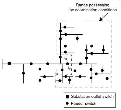
Fig. 21 The range possessing the multistage differential protection coordination
conditions
Where,
r0 is the resistance per unit length and
x0 is the reactance per unit length of the feeder.
According to Equation (22), under different system reactance Xs. Min and wires or cable types, the ratios of critical feeder length to whole feeder length, l C/l total , are shown in Tables 1-3.
The feeder equipped with instantaneous over-current protection is divided into two parts by the critical length l C. When a two-phase short circuit occurs in the upstream part, instantaneous over-current protection of the substation outlet switch will trip and this case does not have the coordination conditions of multistage differential protection. But if a two-phase short circuit occurs in the downstream part, the instantaneous over-current protection of the substation outlet switch will not trip and then over current protection with time delay will start. In other words, the downstream part of the critical point l C on the feeder possesses the coordination conditions of multistage differential protection, as shown in Fig. 21.
It should be noted that the critical length l C is calculated in the maximum operation mode of the system. In the mode of non-maximum operation, the critical length point on the feeder will shift toward upstream, such as point l C' shown in Fig. 22. This shift is beneficial for the coordination of multistage differential protection in the down stream part of the feeder.
The 10 kV feeders are often emitted from the main substation and the power range shows a fan-like distribution under normal circumstances. The closer to downstream, the more branches there are, as shown in Fig. 23. Therefore, for the feeder installed with instantaneous over-current protection, the area processing the coordination conditions of multistage differential protection just lies in the downstream area with more branches.
This condition is beneficial for the coordination of multistage differential protection of substation outlet switch, branch switch, and/or sub-branch switch (or user switch).
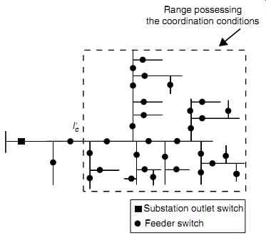
Fig. 22 The upstream shift of a critical length point in the non-maximum
mode operation of the system
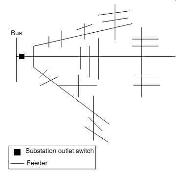
Fig. 23 Fan-like power range of the feeder
4.1.1.3 The Setting of the Time Differential
The analysis here shows that the coordination of multistage differential protection can be implemented along the whole length of the feeder without instantaneous over-current protection, and the coordination of multistage differential protection can be implemented in the downstream part of the feeder with instantaneous over-current protection.
The operating time of the over-current protection of the transformer secondary switch in the substation (i.e., 10 kV bus feeding switch) is generally set to 0.5~0.7 s.
Considering the worst case, in order not to influence the time setting of upper stage protection, it is necessary to arrange the multistage differential protection time delay coordination at intervals of 0.5s.
For the feeder's circuit breaker with a spring-energy-storage operation mechanism, mechanical operation time is generally 60~80 ms and the inherent response time of protection is about 30 ms. Considering a certain time margin, the time differential ?T can be set to 250~300 ms to achieve coordination of two-stage differential protection.
For the feeder's circuit breaker with a permanent magnet operation mechanism, its opening time is about 20 ms. A fast protection algorithm can complete fault diagnosis in about 10 ms. Considering a certain time margin, the time differential ?T can be set to 150~200 ms to achieve the coordination of three-stage differential protection.
If the system has the ability to withstand a greater short-circuit current, the time delay of the over-current protection in the transformer secondary switch can be extended properly in order to improve reliability of multistage differential protection coordination. For example, for the switch with a permanent magnetic operation mechanism, the time differential can be set to 200 ms. For the switch with a spring energy-storage operation mechanism, the time differential can be set to 300 ms.
Generally, the thermal stability check-time of transformer, breaker, load switch, disconnector, line, and the current transformer is 2s. Therefore, the coordination project of multistage differential protection proposed here does not influence the thermal stability of these devices.
4.1.2 Configuration Rules for Multistage Protection based on Time Differential
4.1.2.1 Configuration Rules for Two-Stage Differential Protection
For the coordination of two-stage differential protection, the principles of protection configuration and switch choice are as follows.
1. All trunk line switches adopt the load switch.
2. User switch, branch switch, and sub-branch switch adopt the circuit breaker.
3. The instantaneous over-current protection of the substation outlet switch can be installed as needed, and time delay of the over-current protection is set to one time differential, ?T.
4. For the area possessing multistage differential protection coordination conditions, time delay of over-current protection in the user breaker or branch breaker is set to 0 s. The current setting should be greater than the maximum load current and magnetizing inrush current from unloaded transformer.
The advantages of the two-stage differential protection configuration mentioned here can be seen as follows.
1. When a fault occurs in the branch or user area (or sub-branch), the corresponding branch breaker or user breaker will trip first while the operation of substation outlet switch is not needed. Therefore, this configuration avoids power failure of the whole line and reduces the number of the users who suffer a power failure after the fault.
2. Prevents the multistage switches from tripping at the same time or overrides
tripping. Therefore, this configuration is a simple fault processing procedure, there is a shorter switch operation time, and short restoration time for a temporary fault.
3. The use of load switch reduces the cost compared to the breaker.
4.1.2.2 Configuration Principle of Three-Stage Differential Protection
A typical three-stage differential protection is formed by the 10 kV substation outlet switch, the branch switch, and user switch in the area possessing coordination multi stage differential protection conditions. Time delay of the over-current protection in the user switch is set to 0s and the current setting should be larger than the maximum load current and magnetizing inrush current of the unloaded transformer. The time delay of over-current protection in the branch switch is set to one time differential, ?T, and the current setting should be larger than the maximum load current and magnetizing inrush current of unloaded transformer. The time delay of the over-current protection in the substation outlet switch is set to dual time differential, 2?T.
4.1.3 The Influence of Grid-Connected Distributed Generation
The integration of the distributed generation (DG) may have some impact on the scheme of the multistage differential protection, as mentioned previously.
4.1.3.1 The Influence on the Feeder without Instantaneous Over-Current Protection
For a feeder without instantaneous over-current protection, its multistage differential protection coordination is relatively simple, which can be realized by the coordination of the time delay of over-current protection in the substation outlet switch and branch switch or user switch.
After the access of DG, in the case of a phase to phase fault, the short-circuit cur rent flowing through the substation outlet breaker and each segment switch along the feeder is changed compared with that before the access of DG. On the one hand, when a fault occurs downstream of the DG, it will decrease the short-circuit current flowing through the switch in the upstream of the same feeder, and increase the short-circuit current flowing through the downstream switch. When a fault occurs upstream of the DG, a short-circuit current from only DG will flow through the switches located between the fault point and the DG in the same feeder. On the other hand, the DG in the other feeders can also inject a short-circuit current to this feeder through the same distribution bus, which may lead to a rise of short-circuit current flowing through the substation outlet breaker in the fault feeder and the segment switches at the upstream of the fault point. A short-circuit current contributed to by the DG in the fault-free feeder will flow through its corresponding feeder's outlet breaker. As for the actual increase or decrease of the short-circuit current somewhere in the feeder, it is necessary to comprehensively analyze the impact of these two aspects.
However, because sensitivity of over-current protection is generally high, the DG capacity is generally small, and in particular, the short-circuit current from the inverter based DG is very small, so the DG will not cause maloperation of over-current protection in the upstream switch.
So, for the feeder without instantaneous over-current protection, the access of the DG generally has no influence on its multistage differential protection coordination.
4.1.3.2 The Influence on the Feeder with Instantaneous Over-Current Protection
Provided that a feeder is installed with instantaneous over-current protection, and a DG is connected to an adjacent feeder powered by the same distribution bus. When a fault occurs on this feeder, the current from the DG in the adjacent feeder will expand the protection range of instantaneous over-current protection in the substation outlet switch and its operating zone will extend to downstream of the critical length l C, which is calculated according to the case with no DG, resulting in the increased possibility of an override trip. Therefore, in this case, the area with multistage differential protection coordination needs to be properly adjusted to the downstream.
The DG does not affect instantaneous over-current protection in the same feeder.
If a fault occurs downstream of the DG, the short-circuit current flowing through the substation outlet switch will be decreased, and the protection range of instantaneous over-current protection will be reduced, which is beneficial for the multistage differential protection coordination between substation outlet switch and downstream switch of critical length point l C.
4.1.3.3 Impact of the Reverse Short-Circuit Current from DG on the Multistage Differential Protection
In addition, no matter whether instantaneous over-current protection is installed or not, if a DG provides a larger short-circuit current, it is likely that the over-current protection without directional element of the branch or user switch, and even the substation outlet switch, would not operate properly due to the reverse fault current, and result in a failure of multistage differential protection coordination. For this, it is necessary to selectively configure a directional element in the corresponding switch. However, when the short-circuit current from DG is lower (such as the inverter-based DG, photovoltaic generation, etc.), it has less of an effect in this regard and if necessary, it is feasible to appropriately adjust the current setting of over-current protection rather than installing a directional element.
4.1.3.4 The Influence on Auto-Reclosing
According to the "technical rule for the DG connected to power grid" formulated by the State Grid Corporation of China, it is proposed that the non-islanding DG must be removed from the grid 2s after faulting in the feeder. Therefore, for the switch with a downstream DG, the auto-reclosing delay time should be more than 2s.
4.1.4 Handling Measurement of the Area without Multistage Differential Protection Coordination
For the feeder with instantaneous over-current protection, the upstream part of the critical length point l C does not meet the coordination condition for multistage differential protection. For this part of the feeder, it is feasible to adopt a similar configuration to that described in Section 4.1.2. That is to say, the substation outlet switch, branch switch, and user switch (or sub-branch switch) are replaced by circuit breakers with instantaneous over-current protection. Although an override trip may occur when a fault occurs, it is still beneficial for fault processing with the help of coordination of auto-reclosing, or centralized intelligent fault processing from the distribution automation system's master station. For specific fault processing, refer to Section 3.
4.2 The Coordination of Multistage Protection Based on Three-Section Over-Current Protection in the Distribution Network
Protection relaying with a differential coordination for distribution network cannot achieve the multistage protection coordination for the trunk line. For suburban or rural distribution lines with a longer power radius, when a fault occurs in the trunk line, there is an obvious difference of short-circuit current in each segment switch located upstream of the fault, and it is feasible to coordinate the multistage three-section over current protection.
This section mainly discusses the key problems and improved methods of the coordination of multistage three-section over-current protection for a distribution network.

Fig. 24 Schematic of configurable n-stage protection
4.2.1 Analysis of the Coordination of Multistage Three-Section Over-Current Protection under the Traditional Setting Method
According to the "Setting guide for 3~110 kV power system protection equipment (DL/ T584-2007)" formulated by the State Grid Corporation of China, the current set ting of instantaneous over-current protection (section I) of the traditional three-section over-current protection should be set according to the principle that this protection should not operate when a maximum three-phase short-circuit occurs at the end of the protection zone. The current setting of time delay instantaneous over-current protection (section II) should be set according to the principle of protecting the whole zone at this stage in any fault, and it also should coordinate with section I of the next stage, while sensitivity must be checked according to the minimum two-phase short-circuit current at the end of this stage. The current setting of definite time over-current protection (section III) should be set to avoid protection operation at the maximum load current, so the setting value is relatively small. Section III protection should not only protect the whole length at this stage, but also play the role of remote backup protection in order to protect the whole length of the next stage.
As for the feeder shown in Fig. 24, it is assumed that in-stage protection coordination can be achieved. That is to say, the feeder is divided into n segments, and there are n sets of three-section over-current protection device along the line. The path consists of three-section over-current protection devices at each stage and is called the protection path of the feeder.
Where l n represents the length from a 10 kV substation bus to the end of the nth segment in the protection path, and its equivalent impedance is denoted by Zn , l n' represents the length from 10 kV substation bus to the protection end of section I on the nth segment in the protection path, and its equivalent impedance is denoted by Zn'. Let ln denote the length of the nth segment, it can be expressed as
 (23)
(23)
Provided that system impedance in the maximum and minimum mode is, respectively, denoted by XS.min and XS.max , for the nth-stage instantaneous over-current protection (section I), in any operation mode in which the system impedance is Xs (Xs. Min < Xs < Xs.max ), when a fault occurs at the end of the zone of the instantaneous over-current protection, the short-circuit current I k.n shall be equal to the setting of the nth stage instantaneous over-current protection (section I) I I.op ,
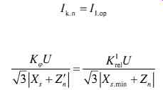 (eq.24,That is: e. 25)
U = the amplitude of the system voltage.
Kf = the coefficient of fault type, Kf = 1 for a three-phase fault, Kf = 0.866 for a two phase fault.
KI rel = reliability coefficient of the protection, usually KI rel = 1.3.
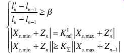
Let ß denote the length ratio of a stage that the instantaneous over-current protection of this stage protection device must protect, That is, when a two-phase short circuit occurs in the minimum operation mode of the system, the length ratio that this segment of the line needs to have to be protected is at least ß, there are:
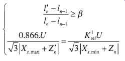
(eq.26)
And it can be rewritten as:
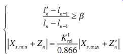 (eq.27)
In order to meet the requirements of reliability coordination, the range of time delay instantaneous over-current protection (section II) of the (n - 1)th stage should be less than the instantaneous over-current protection (Section I) of the nth stage, and its sensitivity Ksen must meet the requirements, namely
 (eq.28)
And it can be rewritten as
Where K? = equivalent coefficient by comprehensively converting, KK KK senrel II rel I Ksen = sensitivity coefficient, generally it is no less than 1.3 I n k. .min 1 2 = the minimum two-phase short circuit current at the end of the (n - 1)th stage of the feeder I II.op.n-1 = the protection setting value of section II of the (n - 1)th stage.
Both the formulas (eq.27) and (eq.29) are the general conditions to achieve the coordination of three-section over-current protection at the nth stage.
Provided that the wire type and its section of the trunk line is the same, and the impedance per unit length is represented by z, then
(eq.30)
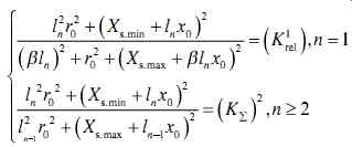
Put Equation (eq.30) into (eq.27) and take a critical value, then the following formula can be obtained,
And put Equation (eq.30) into (eq.29) and take a critical value, then the following formula can be derived,
Where, r0 and x0 are the resistance and the reactance per unit length of the feeder, respectively.
By Equations (eq.31) and (eq.32), the protection range of l n can be calculated separately, and the larger of these two formulas is the minimum length needed to achieve three-section over-current protection coordination of the nth stage.
4.2.2 Analysis of Improved Multistage Protection Coordination based on the Differentiated Settings
The short-circuit type is not considered in the setting of the instantaneous over-current protection (section I) of the traditional three-section over-current protection. The cur rent value is set according to the principle that it should be larger than the maximum short-circuit current of the three-phase short-circuit at the end of the line and sensitivity is checked according to the minimum two-phase short-circuit current. Thus, when a two-phase short circuit occurs, the protection range is relatively small. If the line is very short or the system operation mode varies widely, the protection range may be zero, this will lead to loss of protection function. In particular, in the distribution net work with an overhead line, the two-phase fault occurs in most cases.
In fact, protection relaying devices can easily distinguish the three-phase short circuit from the two-phase short-circuit. If the three-phase short circuit and two phase short circuit are treated separately, the setting value of the instantaneous over-current protection is set with the maximum fault current at the end of the line, and the sensitivity is checked with the minimum fault current, respectively, two different settings can be calculated for the two different faults. Then, in the case of two-phase short circuit, the protection range will be much larger than that obtained from conventional methods. Therefore, the line length or the system operation mode will have little effect on the protection range and the protection reliability can be greatly improved.
Using the approach similar to Section 4.2.1, the general conditions that are needed for configuring the nth-stage improved three-section over-current protection based on the current setting difference between three-phase short-circuit and two-phase short circuit, can be deduced as follows.
Under the conditions that the wire type and section of the trunk feeder are all the same, the minimum length l n needed for this improved n-stage protection coordination based on the current setting difference as before can be obtained by the following Equation (eq.34).
According to this analysis, we can draw out the critical surface of each stage of protection at different system capacity. In the following figures, the system capacity in the minimum operation mode is Smin
= 200~500 MVA, the system capacity in the maximum operation mode is Smax
= 500~1000 MVA, the overhead line is LGJ-240, the geometric distance is 2.5 m, the reliability coefficients are KII rel
= 1.2 and KI rel
= 1.3, respectively, the sensitivity coefficient is Ksen
= 1.5, and ß is 20%. Then in the area above the critical surface, configuration of multistage protection is possible, while in the area below the surface, configuration is impossible. Fig. 25 is the critical surface of the four-stage protection under the traditional setting method, while Fig. 26 is the critical surface of four-stage protection under the improved coordination method.
The comparison of Figs 25 and 26 can help us draw the conclusion that when the system capacity and the power radius are certain, more stage can be configured by the improved setting method based on the fault type than the traditional method, and the instantaneous over-current protection range is greatly increased in the case of a two-phase short circuit.
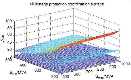
Fig. 25 Critical surface of four-stage protection coordination under the
traditional setting method
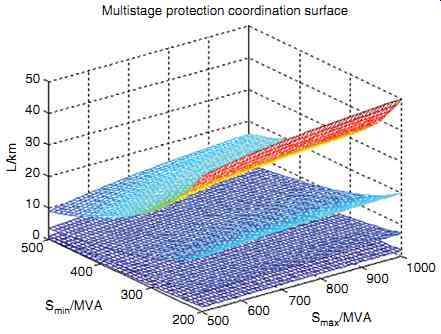
Fig. 26 Critical surface of four-stage protection coordination under the
improved coordination method
4.2.3 Configuration of Multistage Three-Section Over-Current Protection
It is feasible to calculate the desired minimum length l n (i.e., the lower limit of the location of (n + 1)th protection device) of the feeder to configure the n-stage three section over-current protections according to Sections 4.2.1-4.2.2. Then, when the power radius L is certain, the maximum stage number of the three-section over-current protection, which can be configured in this feeder, can be determined.
If l n = L, only nth-stage protection can be installed. In fact, considering an appropriate margin, this condition can be rewritten as 1.05 > L/l n > 1.0.
If l n < L < l n+1
(considering an appropriate margin, such as: 1.0 > L / l n+1 and L / l n > 1.05), the (n + 1) stage protections can be installed. Because the protection range of this stage can't meet the conventional length requirement for a (n + 1) stage, so the (n + 1)th stage of protection is called an "additional stage". Generally the additional stage only sets section I protection for the whole length of just this stage, section II protection is usually uninstalled. In fact, considering an appropriate margin, this condition can be rewritten as 1.0 > L/l n+1 and L/l n > 1.05.
For the multi-source distribution network with a tie line to the opposite side, the stage number of protection should be determined by considering the situation when the tie switch is closing.
For example, for the "hand in hand" ring distribution line, the protection coordination problem of the transferred side feeder should be considered when the tie switch is closed and the feeder load is transferred from one feeder to another feeder to realize the multistage protection. After the tie switch is closed, the power flow direction of the feeder that is transferred has changed, and the relationship between upstream and downstream flow from the switch along the line has changed, so the original properly set current settings are not appropriate anymore.
To solve these problems, it is necessary to install the directional power elements for the hand in hand ring distribution line to achieve multistage protection coordination.
Each protection device is configured with the fault power directional element and, according to the difference in fault power direction, two sets of setting values are adopted. The setting value that is consistent with the normal mode is called the "for ward setting", while the setting value that is not consistent with the normal mode is called the "reverse setting".
The protection stage number of the two directions should be determined by the principles in Sections 4.2.1-4.2.2 under the consideration of the two hand-in-hand feeders comprehensively and the condition that the tie switch is in closed mode. If a protection device doesn't need reverse protection, block the reverse protection directly.
Sometimes, in order to divide the feeder evenly by the additional reverse protection relaying in the opposite side of the feeder, it is also feasible to set up reverse protection separately on the segment switch without forward protection.
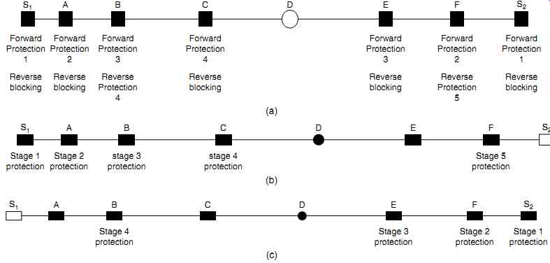
Fig. 27 First example of multistage protection configuration in a "hand-in-hand" ring
network
For example, for the hand in hand ring distribution line shown in Fig. 27(a), S1 and S2 are outlet breakers of the 10 kV substation, A, B, C, E, and F are segment breakers, and D is the tie switch. In this figure, the solid body represents a switch in a closing state, while the hollow body represents a switch in an opening state; a square represents a breaker, while a circle represents a load switch. This assumes that the feeder of S1 configures four-stage forward three-section over-current protection and the feeder of S2 configures three-stage forward three-section over-current protection. According to the analysis, in the condition that the load on feeder S2 is transferred to S1, the reverse protection is set at point F if five-stage protection coordination can be achieved, as shown in Fig. 27(b). Also according to the analysis, in the condition that the load on feeder S1 is transferred to S2, the reverse protection is set at point B if four-stage protection coordination can be achieved, as shown in Fig. 27(c). The reverse protection in the remaining switches should be blocked.
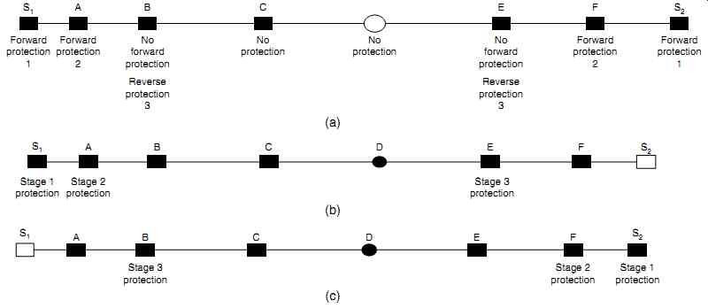
Fig. 28 Second example of multistage protection configuration in a "hand-in-hand" ring
network
What's more, for the hand-in-hand ring distribution line shown in Fig. 28(a), S1 and S2 are outlet breakers of the 10 kV substation, A, B, C, E, and F are segment breakers, and D is the tie switch. In this figure, the solid body represents a switch in a closing state, while the hollow body represents a switch in an opening state. This assumes that the feeder of S1 and the feeder of S2 can both be configured for two-stage forward three-section over-current protection. Although point E does not set forward protection, in the case that the load of feeder S2 is transferred to S1 the reverse protection will be configured at E if the three-stage protection coordination can be achieved, as shown in Fig. 28(b). Although B does not set forward protection, in the case that the load of feeder S1 is transferred to S2, the reverse protection will be configured at B if the three-stage protection coordination can be achieved, as shown in Fig. 28(c).


