AMAZON multi-meters discounts AMAZON oscilloscope discounts
[cont. from part 1]
3. Fault Protection of the Active Distribution Network
With the access of distributed generation (DG), the active distribution network has become the major trend of the grid of the future. For protection of the active distribution network, the existing protection for passive distribution network must be improved adaptively or a new wide-area protection based on artificial intelligence with the help of communication systems and smart distribution network automation devices should be established.
3.1 The Influence of Distributed Generation on Current Protection and the Adaptive Improvement of Protection
The integration of DG changes the structure of the distribution network from a single-ended source system to a multiple-ended source system. This further affects the value and direction of the fault current in a distribution network and causes the existing protection for passive distribution network strategy to be no longer applicable. In this section, the impact of DG in different locations on the traditional current protection in distribution network is analyzed first and then some strategies to overcome these effects are introduced.
3.1.1 Situation 1: DG is Connected to the Distribution Bus
As shown in Fig. 16, DG is connected to the distribution bus. At this moment, the radial single-ended source system for each feeder has not changed. Provided that the fault occurs at the point of F1-F4, respectively, as shown in Fig. 16, the impact of the DG on the protection device is analyzed as follows.
1. Fault occurs in F1 or F3 When a fault occurs in F1 or F3, both the source and the DG provide a short-circuit current to the fault point together. At this moment, comparing with the condition without the DG, the DG increases the short circuit current flowing through P1 or P3. This increase in fault current will help improve the sensitivity of P1 or P3 and clear the fault.
2. Fault occurs in F2 or F4 When a fault occurs in F2 or F4, Both the source and the DG provide a short circuit current to the fault point together. At this moment, comparing with the condition without DG, the DG increases the short circuit current flowing through P2 or P4.
This increase of the fault current will help improve the sensitivity of P2 or P4 and clear the fault.
Problem When a fault occurs in F2 or F4, the fault current flowing through P1 or P3 is increased by the DG. If the capacity of the DG is enough to increase the fault cur rent too much, the instantaneous over-current protection of P1 or P3 maybe be tripped incorrectly and this leads loss of protection selectivity.
Solution
The current setting of instantaneous over-current protection of P1 or P3 must be greater than the maximum short-circuit current when a fault occurs at P2 or P4.
If the short-circuit current from the DG is less than 10% of the short-circuit current from the source (i.e., the stiffness of the DG connected network is no less than 10), maloperation will not occur with a reliability coefficient of 1.3. If necessary, if sensitivity is satisfied, the reliability coefficient of the instantaneous over-current protection of P1 or P3 can be increased properly.
3.1.2 Situation 2: DG is Connected to the Middle of the Feeder
As shown in Fig. 17, a DG is connected to the middle of the feeder. At this moment, the radial single-ended source system of this feeder is changed to a partly double-ended source system. Provided that a fault occurs at the point of F1-F4, respectively, as shown in Fig. 17, the impact of the DG on protection devices is analyzed as follows.
1. Fault occurs in F1 When a fault occurs in F1, both the source and the DG provide fault current to the fault point together. But only the short circuit current from the source flows through the protection of P1 and so P1 will trip to clear the fault. It should be pointed out that the DG must be disconnected from the feeder by itself.
Problem 1
If a nonmetallic fault occurs in F1 and the capacity of the DG is large enough, the DG will increase the current of the fault point and also the fault voltage, this will lead to a decrease in short-circuit current provided by the source, and hence reduce the protection sensitivity of P1. Furthermore, the instantaneous over-current protection of P1 maybe refuses to trip.
Solution 1
A definite time over-current protection can be added as a backup protection of the instantaneous over-current protection of P1. According to the setting principle of definite time over-current protection, its sensitivity is enough to overcome the influence of the DG. Moreover, the capacity of the DG can be limited to increase the stiffness of the network.
2. Fault occurs in F2 When a fault occurs in F2, both the source and the DG provide short-circuit current to the fault point together. At this moment, the short-circuit current from the source and the DG flows through the protection of P2. Comparing with the condition without the DG, the short-circuit current flowing through P2 is increased. Therefore, P2 is able to trip reliably and clear the fault. At the same time, although a short-circuit current also flows through P1, P2 will clear the fault prior to P1 and leaves P1 non-operational due to the coordinated time limit between P1 and P2.
3. Fault occurs in F3 When a fault occurs in F3, both the source and the DG contribute short-circuit current to the fault point together. At this moment, comparing with the condition without the DG, the DG increases the short circuit current flowing through P3. This increase of the fault current will help improve the sensitivity of P3 and clear the fault.
Problem 2
When a fault occurs in F3, the short-circuit current contributed to by the DG flows through P1. This current, if large enough, may cause maloperation of P1 and form a power island composed of LD1, LD2, and DG. Finally, the DG will be disconnected.
Solution 2
An effective method is to add directional over-current protection to P1. The directional device makes P1 trip only when the short-circuit current flows from the source, and avoids the influence of inverse current from the DG. Besides, it is feasible to limit the DG capacity properly and increase the rigidity of the network.
4. Fault occurs in F4
When a fault occurs in F4, both the source and the DG contribute short-circuit cur rent to the fault point together. At this moment, comparing with the condition with out the DG, the DG increases the short circuit current flowing through P4. This increase of the fault current will help improve the sensitivity of P4 and clear the fault.
Problem 3
When a fault occurs in F4, the short-circuit current flowing through P3 is also increased compared to the condition without the DG. The increase of short-circuit current in P3 may cause a maloperation of its instantaneous over-current protection and a loss of protection selectivity.
Solution 3
It is feasible to increase the reliability coefficient of the instantaneous over-current protection of P3 properly. Besides, another effective way is to limit the DG capacity properly to improve the rigidity of the network.
Problem 4
As for Problem 2, when a fault occurs in F4, the short-circuit current contributed by the DG flows through P1. This current, if large enough, may cause maloperation of P1 and form a power island composed of LD1, LD2, and DG. Finally, the DG will be disconnected.
Solution 4
The same as Solution 2. It is feasible to add a directional over-current protection to P1. Besides, it is also effective to limit the DG capacity properly to improve the rigidity of the network.
3.1.3 Situation 3: DG is Connected to the End of the Feeder
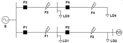
Fig. 18 DG located in the end of feeder
As shown in Fig. 18, here the DG is connected to the end of the feeder. At this moment, the radial single-ended source mode of this feeder is changed to a double-ended source mode. Provided that a fault occurs at the point of F1-F4, respectively, as shown in Fig. 18, the impact of the DG on the protection devices is analyzed as follows.
1. Fault occurs in F1
When a fault occurs in F1, there is no fault current flowing through P3 or P4, but a large short circuit current from both the source and the DG will flow into the fault point and also a large short circuit current from the source will flow through P1, a relatively small short circuit current from the DG will flow through P2.
In this condition, P1 will trip reliably and clear the fault. At the same time, if the short circuit current from DG is large enough, P2 may also trip and isolate the fault point. However, if this current is relatively small or a directional over-current protection is added to P2, the DG should disconnect by itself.
2. Fault occurs in F2
When a fault occurs in F2, there is no fault current flowing through P3 or P4, but a large short circuit current from both the source and the DG will flow into the fault point and also a large short circuit current from the source will flow through P1 and P2.
In this condition, P2 will trip reliably and clear the fault with priority, and DG should disconnect by itself to isolate the fault point.
Problem 1
If a nonmetallic fault occurs in F2 and the DG capacity is large enough to raise the voltage across the fault point, we can deduce which source the short-circuit current flowing through P1 and P2 contributed from. As a the result, protection sensitivity may decrease and the instantaneous over-current protection of P2 loses its function.
Solution 1
It is feasible to add a definite time over-current protection as the backup protection for P1. According to the settling principle of definite time over-current protection, its sensitivity should be enough to overcome this DG influence.
3. Fault occurs in F3
When a fault occurs in F3, both the source and the DG contribute short-circuit current to the fault point together. At this moment, comparing with the condition without the DG, the DG increases the short circuit current flowing through P3. This increasing of the fault current will help improve the sensitivity of P3 and clear the fault.
Problem 2
When a fault occurs in F3, the short-circuit current contributed by the DG flows through P1 and P2. This current, if large enough, may cause maloperation of P2 due to its smaller over-current setting than P1, and thus a power island composed of LD2 and DG will be formed. Finally, the DG will disconnect by itself.
Solution 2
An effective way is to add directional over-current protection to P1 and P2. The directional device makes P1 or P2 trip only when the short-circuit current flows from the source and avoids the influence of inverse current from the DG.
4. Fault occurs in F4 When a fault occurs in F4, both the source and the DG contribute short-circuit current to the fault point together. At this moment, comparing with the condition without the DG, the DG increases the short circuit current flowing through P3 and P4. This increase of the fault current will help improve the sensitivity of P4 and P4 will clear the fault.
Problem 3
When a fault occurs in F4, the short-circuit current flowing through P3 is also increased compared to the condition without the DG. The increase of short-circuit current in P3 may cause maloperation of its instantaneous over-current protection and a loss of protection selectivity.
Solution 3
It is feasible to increase the reliability coefficient of the instantaneous over-current protection of P3 properly.
Problem 4
The same as Problem 2. When a fault occurs in F4, the short-circuit current contributed to by the DG flows through P1 and P2. This current, if large enough, may cause maloperation of P2 firstly, due to the smaller over-current setting than P1, and a power island composed of LD2 and DG will be formed. Finally, the DG will disconnect by itself.
Solution 4
The same as Solution 2. It is feasible to add directional over-current protection to P1 and P2.
This analysis shows that the influence of DG on the protection of distribution systems is closely related to the capacity of DG. If the DG capacity is very small, the influence of DG on traditional current protection can be ignored as long as the function of anti-islanding protection is adopted in the DG. But if the DG capacity is relatively large, it may lead to loss or decrease of protection sensitivity, and furthermore, may cause maloperation of the upstream protection installed in the same feeder or maloperation of protection installed in the neighbor feeders.
To sum up, decreasing DG penetration or capacity and increasing short-circuit capacity and the rigidity of the distribution system are the best strategies to solve the influence of DG on the traditional over-current protection in distribution network.
1. It is feasible to properly improve the reliability coefficient of the instantaneous over-current protection of the breaker near the source. Moreover, it is also effective to set time delay instantaneous over-current protection to make up for the decrease of the sensitivity of instantaneous over-current protection.
2. It is feasible to add a directional element to the over-current protection between the source and the DG. The protection will start only when the short-circuit current flowing from the source is detected.
3. It is also feasible to set a definite time over-current protection as a backup for all the protections between the source and the DG.
4. The grid-connected DG must have the automatic splitting functions of low-voltage, low-frequency, and anti-islanding protection.
3.2 Influence of Distributed Generation on Auto-Reclosure and its Adaptive Improvements
The instantaneous faults make up more than 80% of all the faults in distribution network. Due to this the use of auto-reclosure may greatly improve the reliability of the distribution system. Particularly in a radial single-ended source system, the instant accelerated protection trip with auto-reclosure has been widely used. The major influence of DG on automatic reclosing and the corresponding improvement measures are as follows.
Problem 1
DG enhances arc sustainability of the fault point. If an instantaneous fault occurs in the feeder with DG, the breakers at the source side will trip and then start the function of automatic reclosing. If DG does not disconnect from the line after the fault has occurred and remains to provide current to the fault point instead, the arc will remain in the fault point and therefore leads to the failure of automatic reclosing.
Solution 1
There are several strategies:
1. The converter-type DG must be able to detect the isolated island immediately and then be disconnected from the grid. Meanwhile, the anti-islanding protection time must be less than the reclosing time.
2. The reclosing adopts the strategies of no-voltage checking, which is to ensure reclosure starts only when the DG is disconnected and there is no voltage in the down stream network.
3. It is feasible to install a breaker with directional over-current protection and auto reclosing at the upstream side of the DG connection point. When a fault occurs in the line, the breaker detects the short-circuit current from the DG and then trips first. After that the breaker can't be reclosed until the arc is eliminated and the source restores its service successfully. The current setting of the directional over-current protection should be less than the rated current of the DGs in the downstream line of the protection.
Problem 2
DG may cause a non-synchronization closing of the auto-reclosing device. When an instantaneous fault occurs in the feeder with DG, the breaker at the source side will trip protectively. If the DG does not split from the grid, an isolated island will be formed.
Owing to the non-synchronization between the isolated island and the grid, non synchronized closing will have an unacceptable impact on the grid.
Solution 2
It is necessary for the ARD to have the function of synchronization checking or auto-synchronizing.
Taking the distribution network shown in Fig. 19 as an example, the instant accelerated protection trip of auto-reclosure is installed in P1. For the unimproved system shown in Fig. 19(a), if an instantaneous fault occurs in point k, P1 will trip without selectivity. If P1 recloses the breaker before the DG disconnects from the grid, reclosing will fail due to the sustainable arc. Fig. 19(b) shows an improved system, P3 is the special added breaker with directional current protection and the function of synchronization-checking reclosing, and the current setting is less than the rated current of the DG. If an instantaneous fault occurs in point k, P1 will trip without selection, meanwhile, P3 will trip either due to the fault current from DG, then the fault will be isolated and the arc will be eliminated. P1 will automatic reclose after a time delay, thereafter, P3 will reclose synchronously when the normal source voltage is detected. Finally the power service for the whole system will be restored.
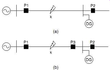
Fig. 19 Influence of distributed generation on auto-reclosing and its
improvement measure
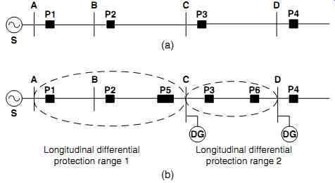
Fig. 20 Configuration of longitudinal current differential protection
in distribution grids with DG
3.3 Longitudinal Current Differential Protection of DG Connected Distribution Networks
This analysis shows that the adaptive improvement for traditional current protection may meet the needs of protection for the distribution network with distributed generation. However, the DG is required to have the function of anti-islanding protection, which makes it split from the grid when the system loses its source. Obviously, the DG loses its contribution to the power reliability of the distribution network and is not suitable for a micro-grid.
In a distribution network with DG or for a micro-grid, installing longitudinal current differential protection in a small area prevents the DG disconnecting from the grid.
The setting principle of longitudinal current differential protection is as follows.
1. Install the protective breakers at both sides of the DG connecting point.
2. Set a longitudinal current differential protection between any two sources (including the distributed generation and the micro-grid) in the feeder.
3. The start condition of longitudinal current differential protection still adopts equation (12), but the minimum current that reflects the unbalanced current must consider the influence of the load in the protection range.
4. It is better to set a single shot reclosing for longitudinal current differential protection, in which the reclosing on the DG side should have the function of synchronization-checking.
5. Directional elements should be added to the definite time over-current protection in the range of the longitudinal current differential protection.
Taking the distribution network shown in Fig. 20 as an example, there are two DGs in the buses C and D of a feeder that can operate in island mode. According to the principles mentioned here, protection at P5 and P6 is added first. Two longitudinal current differential protection configured with auto-reclosing devices are designed, respectively, in the area surrounded by P1-P5 and in the area surrounded by P3-P6.
When a fault occurs in the area 1, first the longitudinal current differential protection of P1 and P5 will clear the fault without time delay, and then the reclosure of protection P1 on the source side begins. If there is a temporary fault, the first reclosing will be successful, then protection P5 will reclose with synchronization-checking and the whole system restore power service. But if the fault is permanent, the protection will operate according to the principle of definite time over-current protection. Protection P2 will trip first if the fault occurs in the area BC, while protection P1 will trip if the fault occurs in the area AB.
When a fault occurs in area 2, first the longitudinal current differential protection of P3 and P6 will clear the fault without time delay, and then the reclosure of protection P3 on the source side begins. If there is a temporary fault, the first reclosing will be successful, then protection P6 will reclose with synchronization-checking and the whole system restores power service. But if the fault is permanent, protection P3 will trip again due to reclosing on the permanent fault.
It is worth pointing out that the current setting of the longitudinal current differential protection should be larger than the maximum magnetizing inrush current of the unloaded transformer, which is located in the differential protection area.
With the help of distributed intelligent control technology in the wide area measurement system and the distribution automation system, the longitudinal current differential protection of the distribution network with distributed generation can be promoted to a wide area current differential protection. A smart terminal unit (STU) is installed on both ends of each longitudinal differential protection; those STUs serve the functions of synchronous measurement and communication and are connected by Ethernet for data sharing. If a fault occurs somewhere in the distribution network, two adjacent STU will exchange fault current information and the protection operating signal to judge where the fault is and take appropriate action.