AMAZON multi-meters discounts AMAZON oscilloscope discounts
Abstract
The connection of distributed generation in traditional single-ended source systems makes it possible to mesh the grid to a multi-ended source network, and the original three-section over-current protection with auto-reclosing will be no longer suitable.
Various improved solutions to deal with the influence of grid-connected DG and inrush current from unloaded transformers, such as adding power direction elements and adopting multistage protection coordination, are proposed in this Section.
Keywords
relay protection, reclosing, three-section over-current protection, multistage protection coordination, distributed generation, differential protection, magnetizing inrush current, second harmonic braking, coordination mode, setting principle
1. Introduction
This Section discusses fault processing based on devices with local intelligence, including two types of automatic switch coordination methodologies: one without communication and one approach requiring high speed, reliable communication systems.
2. Fault Processing Based on Local Intelligence for Distribution Networks
2.1 Auto-Reclosure Control
The Auto-Reclosure Device (ARD) is such an autonomous device that it automatically interrupts and recloses the circuit breaker with a preset sequence of opening and reclosure when a fault occurs in the power line. The installation of an ARD in the distribution network can greatly improve the power supply reliability and reduce outage cost.
More than 80% of faults on overhead lines are temporary faults, which are caused by insulator surface flashover due to lightning, line-to-branch discharge, and/or one line touching another due to high winds or birds. When the fault line is disconnected, the dielectric strength of the fault point will be restored and the fault will be cleared automatically.
Power service will be restored if the breaker recloses automatically at this moment.
ARDs can be divided into three-phase single-shot reclosing, double-shot reclosing, and tri-shot reclosing according to the reclosing times for a fault. Statistics show that up to about 80% of faults can be successfully restored by three-phase single-shot reclosing so, in Asia, power lines of 35 kV and less are usually equipped with three phase single-shot reclosing devices.
ARDs should follow the following basic principles:
1. ARDs should be put into use under normal conditions and should reclose the breaker when it trips due to the relay protection device.
2. ARDs should not reclose the breaker when the operator disconnects the breaker by the control switch or the remote control device and the operator switch onto the fault manually and then trips the breaker by relay protection device.
3. The start condition of an ARD is on the principle of discrepancy, that is, the ARD gives a reclosing operation only when the control switch is on but the breaker is actually off.
4. The operating times of ARDs should be consistent with pre-specified times (such as the single-shot reclosing device can reclose the breaker only once).
5. The operating time of ARDs should be adjustable. These times should be greater than the time needed for a fault breaker and recovery of the dielectric strength of the surrounding medium, as well as for restitution and preparation for reclosing the circuit breaker and operating mechanism once more. Usually, this time is set to 0.5~1.5 s.
6. Once the ARD recloses the breaker, it should be reset automatically and ready for the next reclose.
7. The ARD should coordinate with protection devices in the system to realize the instant accelerated protection trip or the delayed accelerated protection trip.
The operating process of an ARD is as follows: for a radial distribution network, when a fault occurs, the line breaker should be opened first by protection devices, then the Auto-Reclosure Device is started and recloses the circuit breaker again after a preset delay time. If the fault is temporary, reclosing will be successful and hence the power line service is restored. But if the fault is permanent, the protection system will soon let the breaker trip again after reclosure and thereafter the ARD will not reclose the breaker again.
The three-phase single-shot reclosing device is mainly composed of the starting unit, reclosing time unit, single-shot closing pulse unit, blocking device for manual trip, and trip acceleration unit under manual closure on a fault, as shown in Fig. 1. For a permanent fault caused by un-removed ground wire for security and unrepaired defect in the network, the re-trip of the breaker should be accelerated as much as possible to guarantee selectivity, which needs the coordinated operation of protection system and ARD.
Unlike the ARD used in the radial distribution feeder, for the ARD used in the two source distribution network, the following two issues must be considered. (1) The ARD should reclose the breaker only after breakers on both sides of the fault point are tripped in order to extinguish the electric arc and restore the insulation strength.
(2) The breaker must be closed under synchronous conditions in order to avoid electric shock at the moment of closing.
=====
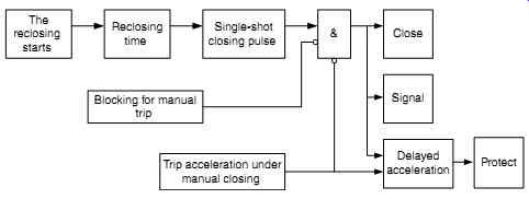
Fig. 1 The principle diagram of three-phase single-shot reclosing
The reclosing starts; Reclosing time; Single-shot closing pulse; Blocking for manual trip; Trip acceleration under manual closing; Close Signal; Delayed acceleration; Protect
=====
2.2 Automatic Backup Switching Control of the Reserve Source
The Automatic Backup Switching Control is also called as the Auto-Put-into Control.
An Auto-Put-into Device of a reserve source (APD) is an automatic control device that, in the two-source system, when one source loses its voltage for some reason, it can switch the loads to another reserve-source automatically, quickly, and accurately in order to avoid interruption of the power supply and significantly improve the reliability of the electric grid.
Generally the connection of the reserve-source can be divided into standby wirings and alternate wirings, which influences the configuration of the APD, as shown in Fig. 2.
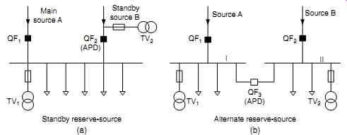
Fig. 2 The wiring of reserve-source (a) and APD configuration (b): Standby
reserve-source; Alternate reserve-source
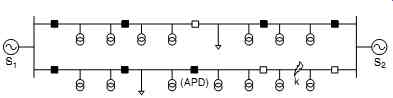
Fig. 3 Tie switches with APD
There are two sources in the standby wiring; one is a main source and the other is a standby source. When the main source outage is caused by fault or maintenance, the standby source is then put to work. As shown in Fig. 2 (a), the APD is installed at the incoming circuit breaker QF2 of the standby source. Under normal circum stances, the bus is supplied by the main source, while the standby source is in standby state due to the breaker opening at QF2. When there is a fault in the main source, the APD will take action, the circuit breaker QF1 will be tripped, the circuit breaker QF2 will be automatically closed, and the standby source will be put to work.
There are also two sources in the alternate wirings, but they respectively provide power to their own loads under normal circumstances and mutually back each other up. When one source is out, its original load will be transferred to the other source.
As shown in Fig. 2(b), the APD is installed at the bus-tie circuit breaker QF3. Under normal circumstances, the bus-tie breaker is in the open state, two sources supply power to the loads connecting to their own bus separately, and they are the reserve source for each other through the breaker QF3. If bus I loses voltage due to a fault at source A, then the APD will take action, breaker QF1 will be tripped, and breaker QF3 will close automatically, thereafter the loads on bus I will be supplied by source B.
The APD of the reserve-source should comply with the following principles:
1. When one source loses its voltage, the APD should disconnect this source and then put the reserve source into service to ensure the power supply is uninterrupted.
2. The APD should not operate if a fault occurs on the load side and causes the source incoming breaker to be tripped by the protection device. The APD should not operate if the reserve source is not in service either.
3. When the working source has a planned outage, the APD shouldn't operate in order to prevent the reserve source from being put to work.
4. When the fuse of the voltage transformer is blown or the voltage transformer is disconnected by a switch, the APD should not operate.
5. The APD should operate only once, in order to avoid the reverse source switching on a permanent fault.
6. The operating time of APD should be as short as possible.
For the tie switch or the section switch in a meshed distribution network, the APD should be allocated. When the original source has an outage because of a source failure, the tie switch or section switch will be turned on automatically by the APD, there after the power service in all areas will be restored automatically by another source on the other side.
For example, as shown in Fig. 3, when the point k of the power line has a permanent fault, the fault area will be isolated by the switch on both sides, then the tie switch with the APD will be closed automatically, and restore power service for the area without fault.
2.3 Voltage Protection
Voltage protection includes over-voltage protection and under-voltage protection.
2.3.1 Over-Voltage Protection
There are two kinds of over-voltage in the distribution network according to the causes of lightning or switch operation. Over-voltage will occur when a lightning strike hits a power line or through a transient process caused by a switch operation in the distribution system.
The means of over-voltage protection in the power line is usually by installing a lightning arrester on the distribution bus or the area close to the protected region. For some voltage-sensitive devices (e.g., electronic devices, distributed generation, etc.), over-voltage protection relays can be installed. When the network voltage is larger than the threshold value, those voltage-sensitive devices will be split from the grid.
2.3.2 Under-Voltage Protection
Under-voltage in the distribution network is usually caused by grid fault or overload.
One method of under-voltage protection is load shedding in the under-voltage condition. As long as the bus voltage is lower than the setting value (e.g., 60% of the rated voltage), the breaker will trip. Another method is instantaneous under-voltage protection with current blocking. When a short circuit occurs in the network, if the important users' bus voltage is lower than 60% of the rated voltage, the fault must be cleared rapidly. The alternate method is over-current protection coordinated with under-voltage starting, if an over-current occurs simultaneously when the voltage decreases or the negative sequence voltage increases, the fault must be cleared rapidly.
For example, provided that the definite time over-current protection and the instantaneous over-current protection are installed at a feeder, because the setting value of instantaneous over-current protection is larger than the maximum short circuit current at the end of the power line, there is a rather large dead zone of the instantaneous protection and hence low sensitivity. When a fault occurs at the rear end of the feeder, it can only be cleared by definite time over-current protection.
Under this condition, in order to improve sensitivity and reduce the dead zone of protection, the setting current can be reduced but, meanwhile, an additional under voltage start-up condition must be adopted (e.g., the voltage is lower than the 60% of the rated voltage) to insure the reliability of instantaneous over-current protection.
2.4 Three-Section Over-Current Protection
Current protection is the most important ways to protect the distribution network.
Almost all faults are accompanied with a surge of current in the power line. At present, there are two main schemes of current protection in the distribution network, three section over-current protection and inverse-time over-current protection.
Three-section over-current protection is composed of instantaneous over-current protection (Section I), time delay instantaneous over-current protection (Section II), and definite time over-current protection (Section III). Fig. 4 shows the operation logic of three-section current protection, where KA denotes the current relay and KT denotes the time relay.
Instantaneous over-current protection is generally set to a value that is larger than the maximum short-circuit current when the fault occurs at the end of the power line.
The instantaneous protection will clear the fault quickly, but it can't protect the whole length of the line and will leave a dead zone of protection.
Time delay instantaneous over-current protection should protect the whole length of the line segment and therefore be set according to the principle that there is enough sensitivity when a fault occurs at the end of its protection zone and this protection should also coordinate with the instantaneous current protection of downstream zone of the line. However, this protection has a time limit to meet the requirement of protection selectivity.
Definite-time over-current protection should also protect the whole length of the line segment and therefore the setting value should be greater than the maximum load current in this line. Definite-time over-current protection for this line segment should also coordinate with the definite-time over-current protection for the downstream segment by an operating time delay to meet the protection selectivity.
Inverse-time over-current protection protects by making the trip time inversely proportional to the short-circuit current in the protected line. That is, the shorter the distance between the fault point and the protection position, the larger the short-circuit current, and the longer the time limit of the protection. The inverse time over-current protection can satisfy the requirements of both rapidity and selectivity.
Definite-time over-current protection and inverse-time over-current protection have their own characteristics. The hardware system of the definite-time over- current protection is more complex than the inverse-time, but the coordination of definite-time over-current protection between the upstream and downstream protection is much easier than inverse-time. With the popularity of computer protection, hardware differences between the protection devices no longer exist, so definite-time over-current protection is more commonly used. However, Section III of the three section current protection can usually be configured as definite-time or inverse-time over-current protection. Inverse-time protection is discussed no further in this Section.
It is worth pointing out that the vast majority of faults in the distribution network are temporary faults. Therefore, for an overhead line network, whatever protection scheme is used, it is necessary to install an ARD to restore power service in the case of a temporary fault.
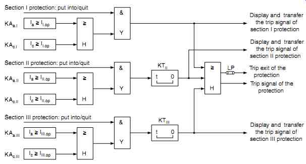
Fig. 4 The operation logic of three-section current protection
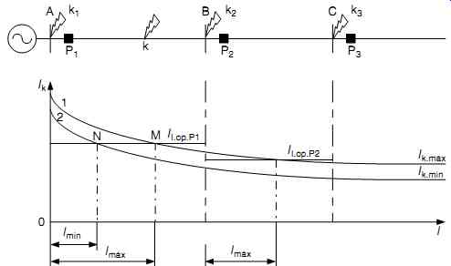
Fig. 5 Instantaneous over-current protection of single-ended radial distribution
network
2.4.1 Instantaneous Over-Current Protection (Section I)
Fig. 5 shows a single-ended radial distribution network. Where curve 1 is the maximum short circuit current I k.max (the three-phase short-circuit current in the maxi mum operating mode of the grid) that varies with fault position k (apart from the source bus A), and curve 2 is the minimum short-circuit current I k.min (the two-phase short-circuit current in the minimum operating mode of the grid) that varies with fault position k.
Instantaneous over-current protection emphasizes selectivity and rapidity. It will disconnect the power line and clear the fault without delay only when a fault occurs on this segment of the line. When instantaneous over-current protection device P1 is installed to protect the line segment AB, P1 must meet the following requirements: P1 should not trip when a fault occurs on the outside of line segment AB (such as a fault occurs on the line segment BC), and P1 must trip when a minimum fault occurs on the head of the line segment AB. Therefore, the operating current of instantaneous over-current protection at P1 should satisfy the following relationship:
I II kI op Pk 21 1 .max .. .min
Where I k1.min
= the minimum short-circuit current at the point k1, that is the short-circuit current when a fault occurs on the point k1 and the grid is in a minimal operation state.
I k2.max
= the maximum short-circuit current at the point k2, that is the short-circuit current when a fault occurs on the point k2 and the grid is in a maximal operation state.
I I.op.P1
= the current setting value of section I or instantaneous over-current protection at P1.
Generally, the operating current of instantaneous over-current protection is set to a value that is larger than the maximum three-phase short-circuit current of the fault occurring on the end of this segment, that is
 (1)
(1)
Where, Krel I is the reliability coefficient of instantaneous over-current protection, generally Krel I 12 13 .~ . .
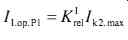
The minimum two-phase short-circuit current at the head of the line is used to verify the sensitivity of this protection,
 (2)
(2)
Where, Ksen is the sensitivity coefficient, generally Ksen = 2.
The actual operating time of instantaneous over-current protection is determined by the inherent opening and operating time of the protection device, which includes the protection exit relays and circuit breakers. The inherent operating time of the exit relay is no more than 25 ms, and the inherent opening time of a circuit breaker is mostly in 30~60 ms. Let t0 denote the inherent opening time of the protection device, which means t I= t0.
As shown in Fig. 5, instantaneous over-current protection cannot protect the whole segment to be protected. l max and l min are the protection range of instantaneous over-current protection under maximum and minimum short-circuit current, respectively. For instance, protection P1 will not trip immediately when a short circuit occurs at the end of the line AB. It means that instantaneous over-current protection has a protection dead zone, and its range depends on the difference of short-circuit current between the head and the end of the protected line. Instantaneous over-current protection may have a long dead zone and then make the protection lose its function in the condition of a short line, a small short-circuit capacity of the system, or big changes to the system operation mode. The faults in the dead zone must be accomplished by time delay instantaneous over-current protection or definite- time over-current protection.
2.4.2 Time Delay Instantaneous Over-Current Protection (Section II)
Time delay instantaneous over-current protection is designed to protect the whole segment of the line and to compensate for the dead zone of instantaneous over current protection. Time delay instantaneous over-current protection can not only be used as a main protection, but also as a backup protection to instantaneous over-current protection.
Taken the network shown in Fig. 5 as an example, assuming that time delay instantaneous over-current protection for the line AB is installed to P1, the protection P1 should trip when the minimum short circuit occurs in the line AB and, meanwhile, the range of protection should be no more than the protective range of instantaneous over-current protection for the downstream line BC (section I in P2). Therefore, the operating current of time delay instantaneous over-current protection at P1 should satisfy the following relationship
I II IopP II op Pk .. .. .min 21 2
Where I I.op.P2 = the current setting value of instantaneous over-current protection at P2 (section I).
I II.op.P1 = the current setting value of time delay instantaneous over-current protection at P1 (section II).
Generally, the current setting value of time delay instantaneous over-current protection must be coordinated with instantaneous over-current protection in the downstream line,
(eq.3)
And sensitivity can be verified by
(eq.4)
Meanwhile, the time limit of the time delay instantaneous over-current protection must be greater than the instantaneous over-current protection in the downstream line: a time difference to meet the selectivity of protection.
(eq.5)
Where Krel II = reliability coefficient of time delay instantaneous over-current protection,
usually Krel II = 1.1 Ksen
= sensitivity coefficient, generally Ksen = 1.5 t I. P2
= time limit of instantaneous over-current protection at P2 t II.P1
= time limit of time delay instantaneous over-current protection at P1
?t = time difference of protection, generally ?t = 0.3~0.5 s
Fig. 6 shows the coordination between time delay instantaneous over-current protection for this segment and instantaneous over-current protection for the next segment.
When a fault occurs at the point k on the line BC, the fault current will start both the instantaneous over-current protection in P2 and the time delay instantaneous over current protection in P1. However, due to the longer time limit of time delay instantaneous over-current protection in P1, the fault will be removed selectively by the instantaneous over-current protection in P2. If P2 refuses to trip for some reason, P1 will clear the fault with a time delay and without selection.
It is worth pointing out that the time delay instantaneous over-current protection may be of low sensitivity and may not protect the whole line where the line is short, there is a small short-circuit capacity of the system, or there are big changes to the system operation mode. Therefore, the definite time over-current protection must be added as a backup protection.
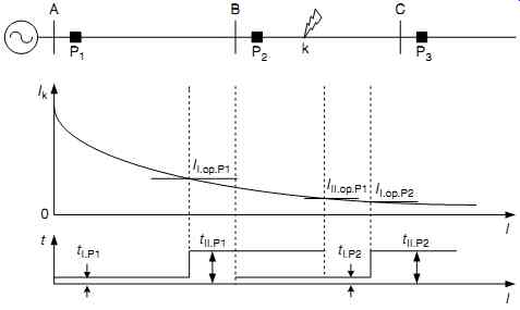
Fig. 6 Coordination of time delay instantaneous over-current protection
with instantaneous over-current protection for next segment.
2.4.3 Definite Time Over-Current Protection (Section III)
Definite time over-current protection is generally used as the local backup protection when main protection in this line refuses to trip and also as the remote backup protection for the next segment of the line. Definite time over-current protection must be able to protect the full length of this segment. Compared with the current protection of section I and section II, Section III has the lowest current setting and the highest sensitivity. The current setting of definite time over-current protection should be larger than the maximum load current, that is:
 (6)
(6)
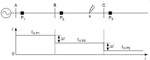
Fig. 7 The scalar principle of the time-delay setting of definite time
over-current protection.
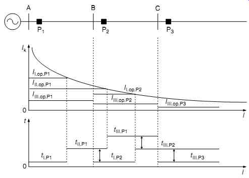
Fig. 8 The coordination of three section over-current protection for a
multi-segmented feeder.
And sensitivity of the protection is verified by the two-phase short-circuit current at the line end under the minimum operating mode,
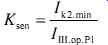 (eq.7)
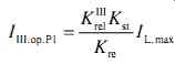
Selectivity of definite time over-current protection is ensured through the time coordination between the two adjacent segment protections. As shown in Fig. 7, according to the time scalar principle, the operating time of section III is set to
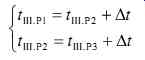 (eq.8)
where Krel III
= reliability coefficient of definite time over-current protection, generally Krel III
= 1.2 ~1.3 Kst
= self-start coefficient of motors Kre
= return coefficient of current relay, generally Kre
= 0.85~0.9 I III.op.P1
= current setting of definite time over-current protection of P1 (section III) I L.max
= maximum load current in the protected line Ksen
= sensitivity coefficients, required no less than 1.5 when the fault is on the end of this segment, and no less than 1.2 when the fault is on the end of the next segment t III. P1
= time delay of definite time over-current protection of P1 t III. P2
= time delay of definite time over-current protection of P2 t III. P3
= time delay of definite time over-current protection of P3.
In order to improve the rapidity of over-current protection, the current protection of section III can also adopt an inverse-time over-current protection. According to the IEC255-4 from the International Electrotechnical Commission, based on the current setting and time setting of the section III current protection, the characteristic of the inverse-time over-current protection is generally expressed as:
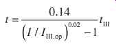 (eq.9)
2.4.4 The Coordination of Three-Section Current Protection
For a single feeder with multi segmented breakers, current protection is installed with all three sections at every circuit breaker. Taking the three segmented feeder shown in Fig. 8 as an example, the protection configuration should comply with the following rules: (1) To design gradually from the terminal of the feeder to the beginning of the feeder; (2) Definite time over-current protection (section III) should be installed first, then the instantaneous over-current protection (section I), and last, time delay instantaneous over-current protection (section II); and (3) If the time limit of definite time over-current protection (section III) is no more than 0.5s, instantaneous over-current protection will be unnecessary.
Only one section, section III, is configured to current protection of P3. The operating current is set to a value of the maximum load current multiplying a reliability coefficient and the time delay is setting to 0 s. It means that the delay time is only the inherent trip time of the protection device.
Two sections, section III and section I, are configured to current protection of P2.
First section III current protection is installed, the operating current is also set to a value of the maximum load current multiplying a reliability coefficient and the operation time delay is set to 0.5 s, which forms a time difference to P3. Section I current protection is also installed in order to improve protection rapidity for a serious fault.
All three sections are configured to the current protection of P1. The operating cur rent of section III is set to a value of the maximum load current multiplying a reliability coefficient and the time delay is set to 1.0s, which forms a time difference to P2. The current setting value of section II of P1 must coordinate with that of section I of P2, and the time limit is set to 0.5 s. The current setting value of the section I current protection of P1 is set to the maximum short circuit current multiplied by a reliability coefficient when a fault occurs at the end of this line segment.
Furthermore, in order to improve temporary fault processing ability, the instant accelerated protection trip of auto-reclosure should be installed to P1.
2.5 Coordination between Current Protection Relaying and Auto-Reclosure
Statistics show that more than 80% of faults on overhead lines are temporary faults.
In order to restore power service as quickly as possible after tripping due to a fault in the distribution network, auto-reclosing devices (ARDs) are usually installed on over head lines to improve the reliability of power supply in the distribution network. In a radial line with multi-stage protection, the automatic reclosing device should be able to coordinate with protection relays to achieve an instant and delayed accelerated protection trip.

Fig. 9 Instant accelerated protection trip
2.5.1 Instant Accelerated Protection Trip
In instant accelerated protection trip, the ARD is only installed to the nearest stage of protection to the power source. As shown in Fig. 9, provided that definite time over current protection is installed at all stage protections of P1, P2, and P3, their operating delay time coordinates by the time scalar principle. No matter where a fault occurs along the line, the fault will be cleared first by the nearest P1 protection breaker with out time delay or selectivity. After that, the automatic reclosing device will reclose the P1 breaker only once, the reclosing will be successful, and power service will P1 (ARD) P2 P3 l 1 l 2 l 3
be entirely restored if the fault is temporary. But if the fault is permanent, the fault will be cleared selectively by the corresponding protection device with a time delay.
Meanwhile, auto-reclosure will be blocked.
Instant accelerated protection trip requires only one ARD and has simple, economical, and rapid characteristics. It can also avoid making a temporary fault into a permanent fault. However, if the fault is permanent, the feeder and loads will suffer short-circuit impact twice over and more time is needed for the second clearing of fault. Instant accelerated protection trip is mainly used in the feeders directly from the substation up to 35kV.
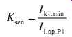
2.5.2 Delayed Accelerated Protection Trip
In the delayed accelerated protection trip, protection devices along every segment of the line are configured with a three-phase auto-reclosing function, as shown in Fig. 10. When a fault occurs on a segment of the protected line, the protection device corresponding to this segment will clear the fault selectively. After then, the ARD will only reclose the breaker once. The reclosing will be successful and power service entirely restored if the fault is temporary, but if the fault is permanent, the protection device will accelerate the trip, let the breaker trip again without time delay and block this auto-reclosure at the same time.
The delayed accelerated protection trip adopts more ARDs and therefore is expensive.
It also needs more time to remove the fault initially. However, the first trip is selective and so the blackout area is reduced. The delayed accelerated protection trip is usually used in the 35 kV and over line, feeding to important loads.
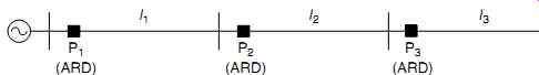
Fig. 10 Delayed auto-reclosing protection trip
2.6 Directional Over-Current Protection
For a two-source distribution line or a single-source ring-network, both ends of the line need a circuit breaker configured to current protection along the power flow direction to meet the requirement of selectivity and isolating the fault area from other similar areas of the network.
Taking the single-source ring-network shown in Fig. 11 as an example, P1~P10 are the segment breakers with protective functions and tie switch LK is closed under normal conditions. Define the power direction from the source to loads as positive, then P1, P3, P5, P7, P9 will provide positive direction over-current protection for feeder 1, and P10, P8, P6, P4, P2 will provide positive direction over-current protection for feeder 2. Only the forward short-circuit current flowing from the protection device can start protection. When a fault occurs on the line (such as F1 in Fig. 11), both breakers around the fault (such as P3 and P4) must be disconnected by directional over-current protection to isolate the fault from other non-faulted segments of the ring-line.
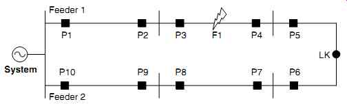
Fig. 11 Directional over-current protection
The setting principles of an operating current with directional over-current protection are the same as those for definite time over-current protection and selectivity is guaranteed by a time delay complying with the scalar principle. The time delay of the protection devices in the ring-line should be satisfied by…
If a short circuit occurs at F1, P1 and P3 will start due to the forward short-circuit current from feeder 1, but only P3 will trip because P3 has a smaller time delay than P1. On the other hand, P10, P8, P6, and P4 will start due to the forward short-circuit current from feeder 2, but only P4 will trip because P4 has the smallest time delay of the four protection devices. Finally, the fault at F1 is isolated by both P3 and P4 with good protection selectivity.
Directional over-current protection can reliably isolate the fault to the smallest area, but its shortcomings are also obvious. First, the closer the fault point is to one source, the longer the tripping time will be. Just as in the example mentioned previously, the operating time t 3 of P3 is longer than time t 4 of P4. Second, directional over-current protection needs an additional directional element and voltage transformer. In particular, the directional element may lose its function if the short circuit causes a very low voltage detected by the protection device. So it is necessary to reduce directional elements.
As shown in Fig. 12, for the network mentioned previously, the only protection points that truly need to install directional elements are P2, P4, P7, and P9. The reasons are as follows: P1 and P10 can only flow their own forward short-circuit current from feeder 1 and feeder 2, respectively, and the time delay is also the longest, so P1 and P10 are unnecessary for installing the directional element. The time delay of P3 is longer than P2. Even if a fault occurs between P1 and P2, P2 will precede P3 to take correct action. Therefore, P3 is unnecessary for installing the directional element. For the same reason, directional elements of P5, P6, and P8 are also unnecessary.
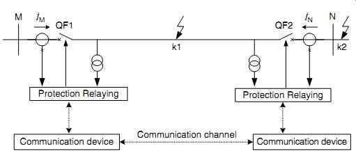
Fig. 13 The schematic diagram for longitudinal current differential protection
2.7 Longitudinal Current Differential Protection
For the over-current protection for single-ended source system mentioned previously, to ensure selectivity, instantaneous over-current protection can only protect a part of the line, so the fault in the dead zone can only be removed by protection with a time limit. But this kind of delay trip is undesirable or not permissible for the important single-ended source system and especially for the double-ended source system.
Longitudinal current differential protection can instantaneously clear a fault in the whole protection zone.
By comparing the value and phase of currents flowing through the two current trans formers on both sides of the line, longitudinal current differential protection can judge whether a fault occurs in the protection zone and will then make instantaneous trip protection. As shown in Fig. 13, longitudinal current differential protection needs to install protection devices at both ends of the protected line, and the communication channel between both ends should be established to exchange current information each other. However, longitudinal current differential protection does not need to coordinate with other protection points in the current setting and time limit.
As shown in Fig. 13, we can define the current flow from the bus of M to N as going in the forward direction first of all, and define the sum of current phasor detected on both bus of M and N as the differential current, denoted I d
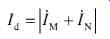 (eq.10)
The current phasor at the both ends of the line
Obviously, the differential current is quite different when the fault occurs in the protection zone (such as k1 ) or outside the zone (such as k2 ). Ignoring the influence of line-to-ground distributed capacitance, when a fault occurs in the protection zone or outside the zone, the differential current will be
I II Ik dM N fault k in the protection zone fault k outside
?? 1 0 1 2d de the protection zone
Longitudinal current differential protection is based on the distinct characteristics of differential current.
Due to the influence of distributed capacitance of the line, the error of current trans formers on both ends of the line, and differences in characteristic of the current relays, the differential current will not be zero during normal conditions, especially for an external fault. This non-zero current is called the unbalanced differential current, and the larger the external fault current is, the larger the unbalanced differential current will be.
To improve the sensitivity of the differential protection for an internal fault and also to suppress the influence of unbalanced current for an external fault, a braking current, denoted I r , is defined as,
 (eq.11)
Therefore, the trip of differential protection should meet the following conditions simultaneously
(eq.12)
= the maximum unbalanced current during normal conditions, usually set to 0.4 times the calculated load current of the line.
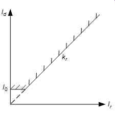
Fig. 14 The characteristic of differential current protection with ratio
restraint
Fig. 14 shows the characteristics of differential current protection with ratio restraint, and the ratio braking coefficient is the slope of the dashed line. The differential current protection should trip when the differential current lies above the dashed line. The double-ended and single-ended source systems will be analyzed, respectively, in the following.
2.7.1 Double-Ended Source System
Provided that the short-circuit currents coming from two sources are the same when the short circuit occurs in the protection zone, both currents are denoted I k. If a fault occurs in the protection zone, the short-circuit current that flows through both M and N buses will be of the same value and the same phase, so the differential current will be 2I k and the braking current will be zero. Obviously, formula (eq.12) is tenable and the differential current will reliably fall in the trip zone. But if a fault occurs outside the protection zone, the short-circuit current that flows through both M and N buses will be of the same value and opposite phase, hence the differential current will be zero and the braking current will be 2I k. In this case, (eq.12) will no longer be tenable.
2.7.2 Single-Ended Source System
If a fault occurs in the protection zone, the fault current I k provided by the source will flow only through the M bus, while no current will flow through the N bus. So the differential current will be I k and the braking current will also be Ik; obviously, Equation (eq.12) will be tenable. If a fault occurs outside the protection zone, fault current I k provided by the source will flow through both M and N buses. So the differential cur rent will be zero and the braking current will be 2I k; obviously, Equation (eq.12) will no longer be tenable.
This analysis shows that longitudinal current differential protection has higher sensitivity in a double-ended source system than in a single-ended source system.
The starting condition of the longitudinal current differential protection shown in the formula (eq.12) can be rewritten as:
(eq.13)
It is worth pointing out that the unbalanced current must be greater than the maximum inrush current of transformer if power transformers are contained in the longitudinal differential protection zone.
Furthermore, the direction of the power flowing through both ends of the line is different when a fault is located in the protection zone or outside the protection zone.
When a fault occurs in the protection zone, the short-circuit power of the two ends flows from both buses to the fault point, then both power flows are in the same direction. But when a fault occurs outside the protection zone, the power flows on the two buses are in opposite directions, one short-circuit flows out of its bus and the other flows into its bus. Based on this power directional characteristic, longitudinal current directional protection can also be constituted.
2.8 The Second Harmonic Braking Criterion in Current Protection
The magnetizing inrush current of a transformer depends on the magnetic characteristics of its core, the remnant flux, the closing initial phase angle, and so on. Under normal conditions, steady main magnetic flux is established in the core of transformer and the magnetic flux density cannot be saturated in the core, so the magnetizing current is very small, usually taking up about 2-10% of the rated current of the transformer.
However, in the temporary process of restorative closing after fault removal or due to a unloaded transformer energizing, the magnetic flux density of the transformer will increase in saturation, resulting in a sharp increase in magnetizing current, the value of which may reach 4~8 times the rated current of transformer.
The magnetizing inrush current may cause incorrect protection tripping, especially for the longitudinal current differential transformer protection and the three-section current protection of a distribution line. Increasing the current protection setting value will decrease or avoid the effect of the magnetizing inrush current of transformer on protection stability, but the protection sensitivity will be reduced. The addition of a time delay on the breaker or over-current protection reclosing device can also prevent false tripping caused by an inrush current at the closing moment, but it also affects rapidity of protection. Therefore, how to identify the magnetizing inrush current from the fault current and distinguish the two is an effective method to find solutions to the influence of magnetizing inrush current on current protection.
By analyzing the magnetizing inrush current of three-phase transformer, it shows that at least one phase current of the three-phase magnetizing inrush current contains a rather large second harmonic component. Therefore, several blocking criteria for magnetizing inrush current based on the second harmonic braking principle have been adopted to prevent false tripping caused by inrush current.
Currently, the main criteria for blocking inrush currents based on the second harmonic braking principle are as follows.
2.8.1 Criterion 1
Take the ratio of the second harmonic component to the fundamental component of the maximum current among the three phase currents as an index. If the index is larger than its setting value, there is a magnetizing inrush current and the trip should be blocked.
(eq.14)
Where I1.max
= fundamental component of the maximum current among the three phase currents I 2
= 2nd harmonic component of the maximum current among the three phase currents Kset
= setting value of second harmonic braking ratio, usually Kset
= 0.15 ~ 0.17.
Criterion 1 uses the information from the fault phase; hence, it is often called fault phase braking. When an unloaded transformer with fault is energized, the current protection will quickly and accurately trip to protect the transformer. However, for the three-phase transformer with the Yd connection, the current measured in the Y side actually is usually the difference of two phase current to ensure the balance of differential current between the Y side and the d side. If the symmetrical inrush current occurs, the second harmonic current may be very small and result in braking failure.
2.8.2 Criterion 2
Calculate the ratio of the second harmonic component to the fundamental component of each phase current, and take the maximum ratio as an index. If the index is larger than its setting value, there is a magnetizing inrush current and the trip should be blocked.
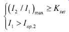 (eq.15)
Where I 1
= fundamental current I 2
= 2nd harmonic current I op.2
= starting current of the 2nd harmonic braking, generally taken as 40% of the calculated load current.
Criterion 2 fully uses the information from the non-fault phases and its index is the maximum value of the three phase ratios, so criterion 2 is also called maximum phase braking. The second auxiliary criterion concerning the fundamental current is used to prevent maloperation caused by a greater calculation error in smaller differential current conditions.
2.8.3 Criterion 3
Take the ratio of the maximum second harmonic component of the three phase currents to the maximum fundamental component of the three phase currents as an index. If the index is larger than its setting value, there is a magnetizing inrush current and the trip should be blocked.
(eq.16)
Where I1.max
= maximum value of the three-phase fundamental currents I 2.max
= maximum value of the three-phase 2nd harmonic currents.
If the inrush current of a three-phase transformer occurs, there is always a larger second harmonic current in at least one phase. Adopting the maximum second harmonic current of the three phases can achieve safe blocking and make up the shortcoming of maloperation in criterion 1 when the symmetrical inrush current arises.
2.8.4 Criterion 4
The second harmonic braking criteria mentioned previously only use the amplitude of the second harmonic component of the inrush current. If the phase information of the second harmonic current is added to the criterion, the brake performance on occasion of smaller second harmonic current can be improved. A new second harmonic braking criterion based on both amplitude and phase information of the inrush current has been proposed in literature. First, the amplitude ratio and the phase difference of the second harmonic current to the fundamental current are defined as follows:
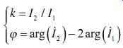 (eq.17)
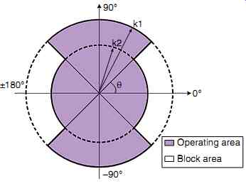
Fig. 15 The braking area based on the amplitude ratio and the phase difference
Fig. 15 shows the scheme of second harmonic braking based on the amplitude and phase information: k1 and k2 are two threshold values of the second harmonic amplitude ratio, respectively. Usually k1 and k2 are set as 0.15 and 0.10, respectively.
? is the margin of the phase difference and usually taken as 30°.
The concrete criterion for second harmonic braking is as follows:
1. The current protection should be blocked if the amplitude ratio is larger than the threshold value k1.
2. The current protection should not be blocked if the amplitude ratio is less than the threshold value k2.
3. If the amplitude ratio is in the range between k2 and k1, whether to block or not is then decided by the phase difference.
Second harmonic braking is mainly used to coordinate with differential current protection of a transformer or a line powered to a transformer in order to prevent maloperation of current protection due to an inrush current from an unloaded trans former. Second harmonic braking can also be used to coordinate with three-section current protection in the medium voltage distribution network to prevent the maloperation caused by the inrush current from transformer without under-voltage protection under conditions of reclosing, especially for the instant accelerated protection trip.
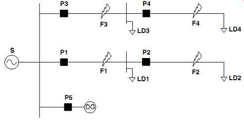
Fig. 16 DG connected to the distribution bus