AMAZON multi-meters discounts AMAZON oscilloscope discounts
4. Relay Application and Principles
The application of protective relays involves factors such as reliability, selectivity, speed of operation, complexity, and economy. Obviously, compromises need to be made among these factors to achieve a protection system that offers the most protection at minimum cost. The information needed to evaluate the application factors is the following:
• One-line system diagram
• Degree of protection required
• Short-circuit study
• Load currents
• Transformer and motor data
• Impedance data for the system equipment
• Operating procedures
• Existing protection and/or difficulties
• Ratios of CTs and VTs
The function of protective relaying can be classified as primary or back up relay protection. Primary relaying is the first line of defense when trouble occurs on the power system. The primary relaying provides the first line of protection and when it fails then back up relaying takes over to provide the second line of protection. Primary relaying should operate as fast as is technically and economically feasible. Prompt removal of faults minimizes equipment damage and helps maintain system stability. Primary relaying may fail because of the following:
• Control power for tripping failure
• Protective relay malfunction
• Breaker failure to open
• Relay and control wiring failure
• CT and/or VT failure
Therefore, back up relaying should be arranged so that anything that causes primary relaying to fail will not cause the back up relaying to fail. Back up relaying should be as completely separated from primary relaying as is possible, including control power, control circuits, and instrument transformers.
The relay operation is a function of the input quantities, such as current, volt age, impedance, and/or phase angle. The relay can be made to respond to either a single quantity or combination of two or all input quantities. When the relay is operated by a single quantity, its response is strictly a function of time, whereas when the relay is operated upon by two or more quantities, its operation is a function of the relative magnitude and phase angle difference of those quantities. Each relay then can be made to respond to its input quantities, known as the operating or relay characteristics. Relay characteristics are very useful in determining the relay setting, which in turn will determine relay speed, sensitivity, and selectivity for protection from power system short-circuits.
Relay application practices can be classified according to relay characteristics and the special requirements of various elements. They are discussed next.
Overcurrent relays
When excessive current flows in a circuit, it is necessary to trip the circuit breaker protecting that circuit. This type of protection is usually provided by either time delay or instantaneous overcurrent relays. The instantaneous relay, although inherently fast, requires a short time to operate, whereas time-delay relays have intentional time delay built into them to provide coordination with other overcurrent relays for selectivity. The selectivity is obtained by adjustment of current setting (sensitivity) and time, using the most applicable of several time characteristics. The relay time characteristics differ by the rate at which the time of operation of the relay decreases as the current increases. The time characteristics for each family of overcurrent relay consist of inverse, very inverse, extremely inverse, definite time, short time, and long time. These curves are shown in FIG. 10. The application of overcurrent relay is generally more difficult and less permanent than that of other types of relaying. This is because the operation of overcurrent relays is affected by variations of short-circuit current magnitudes. These magnitude variations in short-circuit current are caused by changes in power system elements, operation, and system configuration.
Over-under voltage relays
The over-under voltage relays have characteristics similar to the overcurrent relays. The actuating quality in the operating element is voltage instead of current.
Voltage relays often combine the under-over voltage elements in one relay, with contacts for either an undervoltage or overvoltage condition. These relays may be used to trip the breaker or sound an alarm in case of the voltage exceeding a predetermined limit or falling below a predetermined value.
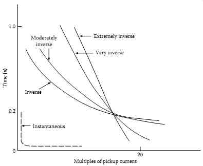
FIG. 10 Time-current characteristics of various families of overcurrent
relays.
Directional relays
Directional relays are used when it is desirable to trip the circuit breaker for current flow in one direction only. That is, the direction is made responsive to the directional flow of power or current. This is achieved by making the relay distinguish certain differences in phase angle between current and reference voltage or current. The directional relay has a current winding and directional winding. The current winding is connected to the CT, whereas the directional winding is connected to the VTs to provide the circuit voltage for polarizing the unit. Therefore, the pickup of the relay is dependent on the magnitude of current and voltage and the phase relationship between them. The directional relay thus establishes one boundary of the protected zone; that is, it protects the circuit only in one direction. Directional relaying is often used where coordination becomes a problem, such as in tie lines between two supply substations or to provide protection against the motoring of a generator.
Current- or voltage-balance relays
Current-balance relays compare the magnitudes of current (or voltage) in two circuits (where these quantities vary within restricted limits) to detect an abnormal condition. The current-balance relay has two torque-producing elements actuated by currents (or voltage) from two different circuits or phases. Current-balance relaying between the phases of a motor is used to protect the machine against overheating in case phase currents become unbalanced owing to short-circuits or fuse blowing. Current balance can be set with sufficient time delay to provide coordination with other relaying.
Distance relaying
The principal application of distance relaying is for transmission lines.
A distance relay operates by comparing the voltage with the current at its location that is measuring the impedance of the line. The relay is designed to operate whenever the impedance under an abnormal condition becomes less than a predetermined value. Since the impedance is a function of line length, the relay operates when a fault (short-circuit) occurs within the given length of line that the relay is set to protect. Distance relays are built in three different types: (1) impedance, (2) admittance (mho), and (3) reactance.
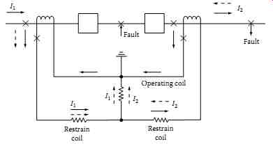
FIG. 11 Typical differential relay connection.
Differential relaying
Differential relaying provides selectivity by providing a zone of protection by correct connection of the CTs. CTs having the same ratio are installed in all the connections to the component to be protected, and the secondaries of the CTs are connected in parallel to the relay restrain and operating coil.
A typical one-phase differential connection is shown in FIG. 11. As long as the current flow through the protected component is unchanged in magnitude and phase, the relay does not pick up. Such a condition would occur for a short-circuit fault outside the zone of relay protection. However, should a fault occur inside the zone of relay protection (that is, between the CTs), the differential relay would receive current in the operating coil.
To obtain differential protection, almost any relay type can be used.
However, differential relays are constructed to provide very sophisticated, fast short-circuit protection. A differential relay has two restraint coils, or more, and an operating coil. The restraint coils prevent the undesired relay operation for fault outside the differential zone, as well as CT errors. Maximum restraint is produced if the current is in the same direction in the two restraint coils, and minimum restraint is produced if currents are in opposite directions in the two restraint coils. The current flowing through the operating coils (i.e., I1 - I2) must exceed a certain percentage of the through current (I2) before the relay will operate. Because it is inherently selective, differential relaying is used as primary relaying on power system components and equipment.
Pilot wire relaying
Pilot wire relaying is a form of differential relaying normally used for protection of longer lines. The pilot wire employs a wire channel to compare currents entering and leaving the protected line between two terminals. The wire pilot channel can consist of the following:
Wire pilot, consisting of a two-wire circuit between the ends of the line.
Carrier-current pilot, wherein one conductor of the line and the earth comprise a pilot circuit for superimposed high-frequency currents.
Microwave pilot, which is an ultrahigh-frequency radio channel between the ends of the line.
For external faults the currents are balanced at the two terminals of the line, whereas for internal faults the currents are not balanced and therefore relay pickup would occur.
5. Types of Relay Tests
The goal of protective relay testing is to maximize the availability of the protection and minimize the risk of undesired operation. Therefore, we must define adequate testing and monitoring methods with appropriate intervals to ensure availability and security are maximized. An electromechanical relay can fail without any external indication. Typically, the only way to detect a failure in an electromechanical relay is through routine maintenance or an undesired operation (i.e., a nuisance-trip or failure to trip). A modern digital relay performs self-diagnostics on key elements to ensure reliable operation.
As a minimum, digital relay self-tests include tests of memory chips, a/d converter, power supply, and microprocessor. However, a digital relay failure may result in an undesired operation if the self-test routines do not detect the failure in time. Most failures are significant enough to either generate a self-test failure or cause the user to recognize the problem during routine operation.
Acceptance tests
When a utility engineer selects a new relay design, it is essential to perform tests of the selected relay to ensure correct operation for the intended application. These tests are referred to as type tests and are usually implemented on a single representative relay from the manufacturer. During type tests, utility staff is introduced to new relay models and functions. If there are specific application questions, utility staff discusses these questions with the relay manufacturer until there is a clear understanding of all the protective functions.
Type tests include detailed tests of the relay characteristics such as mho circle plots, time-overcurrent curve plots, relay element accuracy, etc. The main objective of the type test is verification of the relay algorithms and characteristics.
Commissioning and start-up tests
Utilities typically require tests of each relay prior to placing relays in service.
These tests are referred to as commissioning or installation tests. Once the utility accepts the results of the digital relay type tests, the requirement for commissioning testing is reduced. The operating characteristics of microprocessor-based relays are consistent. This allows us to rely on the type tests for detailed characteristic tests and focus the commissioning tests on simple tests of the relay hardware and implementation of the settings in accordance with the coordination study for the facility or substation.
Relay commissioning tests may be limited to include tests for calibration for implementing the new settings, input/output functionality, simple element accuracy tests, etc. Commissioning tests should also verify the effectiveness of calculated relay element and logic settings. Greater reliance on the type tests for the detailed relay characteristic tests is well justified because those characteristics are fixed in the relay algorithms.
Maintenance tests
The goal of routine maintenance is to verify that the protective relay will not operate unnecessarily and will operate when required. How can routine testing find problems in protective relays? In order to find problems that might be present, it is helpful to examine the type of problems that can occur in both classes of relays. Then, examine the types of tests being performed to see if they are exercising the relays in meaningful ways. Routine maintenance is necessary for the electromechanical relays since these relays are susceptible to environmental contamination and drift over time. These relays should be inspected, cleaned, and calibrated every year or every two years to ensure that they are functioning correctly. The maintenance frequency may be adjusted based on the problems found during the first few maintenance cycles.
Troubleshooting
Digital relays do not require any adjustment or calibration. The manufacturer performs all calibration before the product is delivered, field calibration or adjustment is not required. Digital relays usually include automatic self-test functions. These self-tests verify correct operation of critical relay components. If a self-test detects an abnormal condition, the relay can close an output contact, send a message, or provide some other indication of the failure. The digital relay disables trip and control functions on detection of certain self-test failures. On self-test failure, the relay should be removed from service and returned to the manufacturer for repair.
Electromechanical relays require periodic inspection, calibration, and adjustment. These adjustments may simply be adjustment of the spring tension or as complex as replacing coil, resistors, or capacitors.
Electromechanical relays have been in use for many years and users have developed instructions for troubleshooting techniques for these relays.
Another good source of information is the manufacturer's documentation for a particular device.
6. Testing and Maintenance of Electromechanical Protective Relays
The reliability of protective relays in isolating faulted equipment is dependent on correct installation and maintenance. After protective relays are correctly installed and tested, the maintenance testing objective should be to achieve maximum performance with minimum testing. Relays usually operate for an extremely short time during their long life. Therefore, the question arises as to whether the relay will operate under fault conditions. The answer is to routinely test all protective relays. However, overtesting should be avoided, because testing can potentially add more trouble than is corrected. All relay test programs should include tests that simulate normal operating conditions.
The test program should include acceptance, installation, routine, and repair.
Before meaningful tests can be conducted, advance preparation should be undertaken in order that the testing personnel become familiar with the relays or relay systems.
6.1 Relay Inspection and Tests
General
The installation, maintenance, and small repair testing are done in the field, whereas acceptance and major repair testing are conducted in the laboratory.
To minimize the potential liability of adding trouble to the relays or relay system, the following general procedures are recommended.
Advance preparation
Study the protection scheme (station prints, relay instruction manuals)
Obtain and review results of previous tests and other pertinent information
Arrange for test equipment to perform all tests • Make outage request and switching arrangements • Schedule remote tripping and load tests, when required
Daily preparation
Set up test equipment. Observe precautions in selection and connection to low-voltage service Operating or test personnel perform switching, as arranged, according to approved outage requests Open and isolate, TEST DEAD, and ground if required; place "Keep Out" tag, and report "On" the circuit; complete operating log entries.
If test personnel are not present when switching is performed, verify the isolation, grounding, tag placement, and TEST DEAD before reporting "On" the circuit.
Isolate control circuits; that is, remove control fuses, open test switches, and/or operate selector controls as required. Caution: Be aware of overlapping and interconnecting protective circuits associated with operating equipment. Take measures necessary to keep such schemes in operation. Isolate control, current, and voltage transformer secondary circuits to protect against an unintentional operation from tests on the tagged circuit.
Tests and inspections
Perform and record results of as found tests. Confirm calibrations and settings with a system protection study or relay setting and manufacturer's instructions. Record any defects found; discrepancies should be reported promptly to a supervisor or person in charge and resolved, if necessary.
Verify printed information on the routine inspection sheet (RIS) test forms from previous tests. Prepare other RIS forms, if required.
Perform visual and mechanical inspections.
Check tightness, clearance of exposed lugs, and condition of wiring on panels and switchboards. Check clips of fuse holders for tightness and alignment.
Inspect and perform minor repairs on relays and auxiliary devices. Observe clearances, mechanical freedom, condition of contacts and control springs, condition of internal insulation, and tightness of internal connections. Clean magnets. Check targets and reset mechanisms. Clean glass covers, inspect and replace cover gaskets as needed.
Inspect and test CT and VT, related auxiliaries, and associated wiring.
Inspect for evidence of corona.
Check nameplate information with test forms and other data sources available on the equipment.
Perform CT secondary winding impedance and continuity (backfeed test).
Electrical tests on VT secondary windings normally are not necessary.
VT performance is assured by in-service observations and primary fuse monitoring schemes.
Perform "as left" relay tests. Record results on test forms. Make necessary electrical and mechanical adjustments to achieve desired results.
Calibrate local indicating and recording instruments, and adjust as necessary. Record results on instrument test forms. Calibrate and adjust supervisory telemetering transducers.
Perform complete tripping and operational tests to verify all control and protective functions and alarms. Include supervisory, remote tripping, and bus differential trip circuits.
Complete test forms. Make necessary corrections for circuit designation changes and other changes that may have occurred but were not previously recorded. Include man-hours required to make the tests.
After completion
Replace covers, switchgear plates, remove test leads, jumpers, and separators, close test switches, replace fuses, inspect circuit equipment, and set up control and selector switches preparatory to switching.
Make inventory of tools, jumpers, separators, instruments, and other equipment used. When completed, instruct crew members to consider the circuit as energized and the tag holder to advise that he is ready to report "Off" the circuit.
Report "Off" the circuit and arrange for circuit restoration.
• Operating or testing personnel remove protective grounds and perform switching to restore the circuit to service.
• Perform desired tests under load. Replace covers when completed.
• Restore all station controls to normal, complete station operating log and "Keep Out" tag entries.
• After tests completed on all circuits
• Most of the following items may be performed progressively during the total test period.
• Make necessary field corrections to station prints. Arrange for follow up in order that corrections are made in permanent records.
• Arrange for necessary changes or additions to panel or other circuit designations.
• Complete entry of the relay test records in station ledger if such a ledger is available.
• Prepare a list of items that were not complete or tests not performed.
Include items that may need to be referred to other groups. Submit this list along with completed test forms to your supervisor or persons in charge.
Inspect station to confirm that prints and records are secured and various equipment accessories and spare parts are correctly stored.
6.2 Protective Relay Test Procedures and Circuits
The testing of protective relays and associated circuitry can be carried out by following recommendations outlined in manufacturer's bulletins or the user's own test procedures. These procedures should always be updated based upon a review of past relay performance, test equipment evaluation, and testing methods.
The test interval can be adjusted based upon experience. Otherwise, testing of relays on a yearly or two yearly bases is recommended. The test methods used for relay testing consist of relay functional tests (i.e., relay equipment is separated from power equipment) and only secondary tests are made. The following general guidelines are recommended for electrical testing of protective relays, associated instrument transformers, and wiring.
General protective relay calibration and checklist Perform insulation resistance test on each relay coil to frame. Do not perform this test on solid-state relays. Check manufacturer's instructions to verify if any other precautions are required.
Perform the following tests on the nominal settings specified.
Pickup parameters on each operating element.
Timing tests should be performed at three points on the time dial curve.
Pickup target and seal-in units.
Special tests as required to check operation of restraint, directional, and other elements per manufacturer's instruction manual.
A zero check test should be conducted on any relay that has a time dial. The purpose is to determine proper time dial position when the relay is fixed and moving contacts are closed by the manual rotation of the time dial toward zero.
Perform phase angle and magnitude contribution tests on all differential- and directional-type relays after energizing to vectorially provide correct polarity and connection.
6.3 Relay Test Points and Test Circuits
Time Overcurrent Relays
Most of the time overcurrent relays have three torque-producing elements.
They are control spring which restrains the unit from operating and is the fine adjustment for pickup current; the drag magnet which retards the unit's operating time; the "U" or the electromagnetic which produces operating torque and is the coarse adjustment for pickup. The shape of the time-current curve is essentially a function of the electromagnetic iron circuit. As the cur rent through the coil increases, the flux increases, thereby increasing the torque and thus decreasing the operating time. However, at current levels above pickup, the iron begins to saturate, resulting in less torque (flux) being produced for a corresponding increase in current. Also, the effect of iron saturation is to produce nonsinusoidal currents. Thus the relay operating time becomes fixed (i.e., time-current curve flattens out) regardless of cur rent magnitude. The saturation of the iron increases the reluctance of the iron and thus flux is spilled out of the iron. The relay case normally acts as a shunt for this flux and the flux is passed through the case and not through the relay disk. If the relay is tested in its case, the relay published time-current curves will be duplicated and in-service conditions duplicated as well. However, if the relay is tested outside its case, the published time-current curves may not be duplicated including the service conditions accurately. Therefore, from a preventive maintenance point of view, testing the relay out of the case can yield results that will not check the performance of the relay accurately for in-service conditions, or previous and future results.
The first test on the overcurrent relay should be to check minimum pickup.
Pickup is defined as that value of current which will just close the relay contacts with the relay set at the lowest time dial position. The minimum pickup should be within ±5%.
The next test should be to check the relay calibration at minimum of three timing points, such as at 2 × tap, 4.5 × tap, and 6 × tap settings. The periodic inspection pickup tolerance is ±5% of tap value for non-geared relays and ±7% for geared relays. For new relays, the tolerance is ±1% of tap value. Check the relay for dropout or reset by reducing the current until the relay drops out or fully resets. This test will indicate excessive friction in the jewel bearing.
If the relay is sluggish in resetting or fails to reset completely, then the jewel bearing and pivot should be inspected for cracks in the jewel and dirt. If dirt is the problem, the jewel can be cleaned with an orange stick while the pivot can be wiped clean with a soft, lint free cloth.
Check the instantaneous unit pickup by gradually applying the current.
Also check the target seal-in unit by blocking the main overcurrent contacts.
The testing of an overcurrent relay is done one phase at a time. The ground relay is tested similarly to the phase relays.
Directional overcurrent relays
The overcurrent unit of a directional relay should be checked similarly to the overcurrent relay, with the directional unit blocked closed. The directional relay should be tested for minimum pickup, maximum torque angle, contact gap, and clutch pressure. If the phase power supply is not available, the directional unit can be tested by applying single-phase voltage and current in phase. Usually, this test will give large variations in in-phase pickup, because of in-phase angle being far different from maximum torque angle.
Differential relays
The test conducted on differential relays is to check minimum pickup values using operating and differential currents. The slope (differential characteristic) and harmonic restraint should also be checked. It may also be desirable to trip all circuit breakers from differential relays as a regular testing procedure.
Distance relays
The distance characteristics of the relay are checked near the fault and load angles. Similar to the directional overcurrent relays, the pickup, maximum torque angle, clutch pressure, and contact gap tests should be made.
Pilot wire relays
The pilot wire relay schemes should be tested for shorts, continuity, and grounds in the pilot wires. The operating values are checked along with supervisory and alarm relays used in pilot wire schemes.
Plunger-type relays
These types of relays are instantaneous and/or auxiliary relays, such as PJC, SC, HFA, etc. These relays are tested for operating pickup and dropout values by gradually increasing of decreasing the operating current or voltage.
Current-balance relays
Check pickup of each coil as explained under section on overcurrent relays.
Check for no-trip condition by applying equal amounts of current to opposing coils. Also check operation of the target indicator coil similar to an over current relay.
Overvoltage relay
Check minimum pickup of overvoltage coil similar to overcurrent relays. Select three timing points on the specified time dial. Pickup and timing points should be within ±1% for new installations and within ±5% on existing installations.
Check the instantaneous (if applicable) pickup and target indicator coil.
Undervoltage relay
Check dropout of relay and time relay trip when voltage is suddenly reduced from rated voltage to dropout voltage settings or to zero. Dropout and timing points should be within ±1% for new installations and within ±5% for existing installations. The instantaneous unit should be checked for dropout and target indicator coil.
Thermal overload relays
The thermal overload relays minimum pickup value should be checked using some convenient multiple of tap settings. Because of long time characteristics, the relay pickup point below 200% of tap setting may take a considerable time. Therefore, for test purposes, check pickup at about 200% to 400% of tap settings. Similar to overcurrent relays, the relay time should be checked for several points on the time dial curve. The acceptable time should be within ±10% of specified values. Also check the instantaneous pickup values and target indicator coil.
Voltage-restrained or voltage-controlled overcurrent relays
The overcurrent unit is checked and calibrated much the same as a simple time overcurrent relay. In the case of a voltage-restrained relay, the current pickup of the relay will change with the voltage applied to the voltage sensing coil.
In the case of the voltage- or torque-controlled relay, the overcurrent element will not function at all until the voltage element drops out. Care should be taken when working with any of the voltage circuits on switchgear where these relays are applied because loss of sensing voltages will cause the relays to operate on what would otherwise be considered normal current flow.
Under-over frequency relays
The settings for these relays must be derived by a careful, engineering analysis; and not be guessed at or estimated as they will affect the entire system's continuity of service. The relays generally require three calibration functions: (1) voltage cutoff or drop out; (2) over or under frequency pickup points; and (3) time delay before trip after frequency set point has been sensed. The delay times are not necessarily equal.
Synchronism check relays
Setting and calibrating these relays requires test equipment similar to that used in distance relaying. The permissible window of the angle between the bus and line voltages must be accurately determined during the calibration or maintenance tests. These relays generally have delay times associated with the angle pickup points, and a set of condition switches that dictate relay action when one or more of the sensing voltages is (are) not present.
6.4 Instrument Transformers Calibration
As part of the relay testing and calibration, instrument transformers, such as CT, VT, and capacitive potential devices, should be given excitation, ratio, polarity, and continuity checks. These tests are discussed in detail in Section 2 however a brief overview of these tests is as follows:
Ratio check-CTs
The connections for the ratio check test are shown in FIG. 12. Apply current to the primary to give 1 A in the secondary. For example, in the connection diagram, 120 A is applied to the primary of a 600/5 CT. For a correct ratio check, 1 A should be measured by the ammeter connected in the CT secondary circuit.
Polarity check
The connection diagram for polarity check is shown in FIG. 13. The negative side of the 7.5 V battery is connected to the nonpolarity side of the CT. Connect a DC voltmeter or low-reading ammeter in the secondary of the CT; the positive side of the battery terminal is left unconnected. To verify polarity connections, momentarily touch the battery positive terminal as shown in the diagram.
If the meter needle deflects in the positive direction, polarity is true as connected. If the meter needle deflects in the negative direction, then polarity connections are not as shown connected.
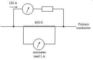
FIG. 12 CT ratio check.
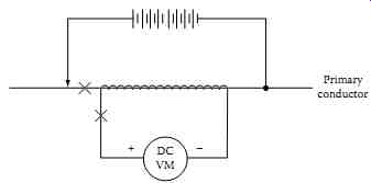
FIG. 13 CT polarity check.
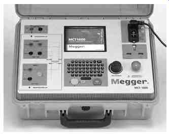
FIG. 14 MCT-1600 test set for testing CTs. (Courtesy of Megger/Programma,
Valley Forge, PA.)
The tests for CTs discussed above may be conducted using a CT test sets made by Megger Limited. These test sets are model CTER-91 and MCT-1600 which are very portable, and use the voltage comparison method for testing CTs. Both of these models can be used to test single and multiratio CTs in accordance with IEEE Standard C57.13.1 using a variable voltage source and precision instrumentation.
These test sets can automatically perform saturation, ratio, and polarity tests all at the same time and display results, including saturation curves on a graphical display. Test results can also be printed directly or stored in an electronic file for future comparison or trending purposes. The MCT-1600 is a newer test set which can produce up to 1 A at 1600 V and up to 5 A at 40 V. This allows saturation testing of most large bushing CTs and burden testing of external CT load circuits. Multiratio CTs should be tested on the individual taps to verify specific saturation and ratio settings applicable to desired relaying schemes.
All of the three tests discussed above, saturation, ratio, and polarity, can be performed without changing any leads. The advantage of using these test sets is that CTs may be tested in their equipment configuration, such as being mounted in transformers, oil circuit breakers, or switchgear. This eliminates the need to remove bushings or remove CTs from their mounting. Of course, it is necessary for the equipment to be deenergized and totally isolated from the electrical system prior to making these tests. The MCT-1600 model is shown in FIG. 14.
Grounding CT and VT circuits
The CT and VT circuits should be grounded at only one point. Relay misoperations can be caused by grounding the neutral at two points, such as one ground at the switchyard and another at the relay panel. At least once every 3 years with the primary de-energized, the known ground should be removed and the overall circuits should be checked for additional grounds and insulation breakdowns.
Open-secondary circuits
WARNING: Secondary circuits of CTs must not be open while primary cur rent flows. Extreme care should be taken to avoid breaking the secondary circuit while primary current is flowing. If the secondary is open-circuited, the primary current raises core flux density to saturation and induces a high voltage pulse in the secondary every half cycle. This high voltage pulse can be four to six times normal voltage and can endanger human life, and damage connected apparatus and leads. If it is necessary to change secondary conditions while primary current is flowing, the secondary terminals must be short-circuited while the change is being made. Caution should be exercised when working with differential circuits as shorting a CT in an energized differential relaying circuit could result in a relay operation. It is recommended that the secondaries of all CTs be kept short-circuited at all times when not installed in a circuit such as being held in stock or being transported.
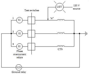
FIG. 15 Continuity check for CTs and associated wiring.
Continuity check (backfeed test)
This test is conducted to check the CT windings and the wiring from test switch to CT (backfeed) for the three phases. The relay test connection diagram is shown in FIG. 15. Conduct tests as follows:
Apply 120 V low current (about 3 A) or a 20 V source with a 100 W lamp at point A. Point A is the test switch location where the protective relay is isolated from CTs with the relay ground maintained.
If the lamp has no glow or no current reading is observed, the CT windings are checked.
Next, jumper to ground the hot side of the CT. The lamp will glow brightly (or 3 A will read on low-ampere source). This indicates that relay circuit wiring is continuous without any shorts or open.
Measure the insulation resistance of transformer secondary windings and CT leads with a 500 V megohmmeter.
Measure the transformer primary insulation with applicable potential test apparatus.
Repeat the preceding test to check all three phases.
Verify the connection of the secondary VT leads by applying a low voltage to the leads and checking for this voltage at applicable devices.
Check for a VT secondary load with secondary voltage and current measurements. Make sure that the load is less than the rating of the VT.