AMAZON multi-meters discounts AMAZON oscilloscope discounts
1 Introduction
This section covers direct current (DC) tests ordinarily performed in the field for acceptance and maintenance of electrical equipment and apparatus.
The information provided by these tests will indicate whether any corrective maintenance or replacement of installed equipment is necessary, assess if the newly installed equipment can be safely energized, and chart the gradual deterioration of the equipment over its service life.
The DC test methods discussed in this section cover transformers, insulating liquids, cables, switchgear, motors, and generators. It is important to have the proper equipment and trained operators when conducting these tests.
Also, if any test is to provide optimum benefits, it is essential to record all test data and maintenance actions for further analysis and future reference.
Furthermore, the test equipment should be maintained in good condition and used by qualified operators. When test equipment is used to calibrate other equipment, it should have twice the accuracy of the equipment under test. Moreover, the test equipment should be calibrated at regular intervals to assure the accuracy of test data.
The test voltage levels and methods, as described in this section, are mostly in accordance with industry standards for the types of equipment discussed.
The DC voltage values correspond to the alternating current (AC) test volt ages as specified by the applicable industry standards. It is recommended that the manufacturer of the equipment be consulted for specific test and test voltage levels when the exact construction of the equipment under test is not known. Where definitive information for a particular equipment cannot be obtained, it is advised that the suggested DC test voltage be based on the rated AC circuit voltage in order to avoid possible damage to the insulation system. It is also important to observe certain additional precautions when conducting DC high-voltage tests; these are listed in Sections 11.
Electrical phenomena in insulation when subjected to DC voltage were briefly discussed in Section 1. Before discussing various DC voltage tests, we need to understand better the electrical phenomena in dielectrics when subjected to DC voltage, which are discussed in the following section.
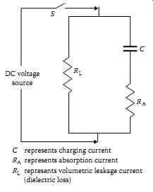
FIG. 1 Electrical circuit of insulation under DC voltage test.
2 DC Voltage Testing of Insulation
When DC voltage is applied to an insulation, the electric field stress gives rise to current conduction and electrical polarization. Consider an elementary circuit as shown in FIG. 1, which shows a DC voltage source, a switch, and an insulation specimen. When the switch is closed, the insulation becomes electrified and a very high current flows at the instant the switch is closed. However, this current immediately drops in value, and then decreases at a slower rate until it reaches a nearly constant value. The current drawn by the insulation may be analyzed into several components as follows:
- Capacitance charging current
- Dielectric absorption current
- Surface leakage current
- Partial discharge current (corona)
- Volumetric leakage current
Capacitance charging current: The capacitance charging current is high as the DC voltage is applied and can be calculated by the formula:
where:
… ie is the capacitance charging current E is the voltage in kilovolts R is the resistance in megohms C is the capacitance in microfarads t is the time in seconds e is Napierian logarithmic base.
The charging current is a function of time and will decrease as the time of the application of voltage increases. It is the initial charging current when voltage is applied and therefore not of any value for test evaluation. Test readings should not be taken until this current has decreased to a sufficiently low value.
Dielectric absorption current: The dielectric absorption current is also high as the test voltage is applied and decreases as the voltage application time increases, but at a slower rate than the capacitance charging current. This current is not as high as the capacitance charging current. The absorption current can be divided into two currents called reversible and irreversible charging currents. This reversible charging current can be calculated by the formula:
where ia is the dielectric absorption current V is the test voltage in kilovolts C is the capacitance in microfarads D is the proportionately constant T is the time in seconds n is a constant
The irreversible charging current is of the same general form as the reversible charging current, but is much smaller in magnitude. The irreversible charging current is lost in the insulation and thus is not recoverable. Again, sufficient time should be allowed before recording test data so that the reversible absorption current has decreased to a low value.
Surface leakage: The surface leakage current is due to the conduction on the surface of the insulation where the conductor emerges and points of ground potential. This current is not desired in the test results and should therefore be eliminated by carefully cleaning the surface of the conductor to eliminate the leakage paths, or should be captured and guarded out of the meter reading.
Partial discharge current: The partial discharge current, also known as corona current, is caused by overstressing of air at sharp corners of the conductor due to high test voltage. This current is not desirable and should be eliminated by the use of stress control shielding at such points during tests. This current does not occur at lower voltages (below 4000 volts), such as insulation resistance test voltages.
Volumetric leakage current: The volumetric leakage current that flows through the insulation volume itself is of primary importance. This is the current that is used to evaluate the conditions of the insulation system under test. Sufficient time should be allowed for the volumetric current to stabilize before test readings are recorded. The total current, consisting of various leakage currents as described above, is shown in FIG. 2.
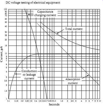
FIG. 2 Various leakage currents due to the application of DC high voltage
to an insulation system.
2.1 Dielectric Phenomena and Polarization
The dielectrics have the property of both temporary and permanent absorption of electrical charges and property of conduction. When a voltage is applied to a dielectric, forces on the positive and negative charges inherent in the particles which make up the dielectric tend to orient the particles in line with the applied field. Some dielectric materials have molecules that have uneven number of atoms, that is, having asymmetrical arrangement of charges. When such a molecule is placed in an electrical field, it will migrate in an electric field, thus become polarized with the electric field. Such a molecule is called a dipole. Dipoles play an important role in the electrical characteristics of the insulation. A dipole may be represented by a particle having small positive charge at one end and a small negative charge at the other end. When these dipoles are subjected to DC voltage, they are polarized and become aligned with respect to positive and negative polarity of the DC voltage. This phenomenon is known as dipole polarization. Polarization phenomenon is influenced strongly by the material properties, structure, and condition of the insulation.
On the other hand, charged particles, that is, particles with positive and negative charges, which are not interrupted by interfacial barriers, and can travel through the dielectric from one electrode to the other, constitute the leakage current, and are not part of the polarization phenomenon.
After a time when the applied voltage is removed from the dielectric, the polarized molecules will eventually revert to their initial random arrangement so that the polarization approaches zero. The time it takes for the polarization to drop to zero when the dielectric is short-circuited is known as relaxation time. It should be noted that the large dielectrics have a much longer relaxation time, and appropriate measures should be taken to discharge the released energy (voltage and current) to ground, which is given by the polarized molecules when they revert to their original state.
2.2 Advantages and Disadvantages of DC Voltage Testing
DC voltage testing is commonly used for testing of electrical equipment and apparatus. DC voltage testing has advantages and disadvantages which vary in importance with the specific circumstances. The advantages and disadvantages of DC voltage are summarized below.
2.2.1 Advantages
DC test is preferred on equipment whose charging capacitance is very high, such as cables.
DC voltage stress is considered much less damaging to insulation than AC voltages.
Time of voltage application is not as critical with DC voltage as with AC voltage.
Test can be stopped before equipment failure occurs.
Measurements can be taken concurrently.
Historical data can be compiled and made available for evaluation.
It is not necessary to make a separate insulation resistance test prior to making a DC overpotential test.
Size and weight of equipment is significantly reduced compared to AC voltage test.
2.2.2 Disadvantages
Stress distribution for transformers, motors, and generator winding is different for DC voltage than is for AC voltage.
Residual charge after a DC voltage test must be carefully discharged.
Time required to conduct a DC high-potential (hi-pot) test is longer than for an AC hi-pot test.
Literature governing DC testing of cables suggest possible harmful effects hi-pot DC testing may have on some types of cables.
Defects, undetectable with DC, can cause failure under AC voltage test.
Voltage may not stress uniformly the insulation system.
Temperature and voltage dependence of resistivity.
Space charge formation-future potential failures.
3 DC Testing Methods
After seeing how insulation behaves when DC voltage is applied to it, let us now take a look at the various tests that are conducted with this voltage. Two tests can be conducted on solid insulation with the application of DC voltage:
- Insulation resistance testing
- High-potential (Hi-pot) voltage testing
3.1 Insulation Resistance Testing
This test may be conducted at applied voltages of 100-15,000 V. The instrument used is a megohmmeter, either hand cranked, motor driven, or electronic, which indicates the insulation resistance in megohms. An electronic megohmmeter is shown in FIG. 3a. The quality of insulation is a variable, dependent upon temperature, humidity, and other environmental factors.
Therefore, all readings must be corrected to the standard temperature for the class of equipment under test. The temperature correction factors for various electrical apparatus are shown in TABLE 1. The megohm value of insulation resistance is inversely proportional to the volume of insulation being tested. As an example, a cable 100 ft. long would have one-tenth the insulation resistance of cable 1000 ft. long, provided other conditions were identical. This test can be useful in giving an indication of deteriorating trends in the insulation system. The insulation resistance values by them selves neither indicate the weakness of the insulation nor its total dielectric strength. However, they can indicate the contamination of the insulation and trouble ahead within the insulation system if a downward trend continued in the insulation resistance values.
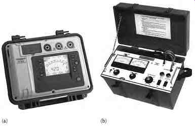
FIG. 3 (a) Electronic megohmmeter, 5000 V and (b) 15 kV DC dielectric
test set. (Courtesy of Megger, Inc., Valley Forge, PA.)
Insulation resistance measurement values can be accomplished by four common test methods:
- Short-time readings
- Time-resistance readings (dielectric absorption ratio [DAR] test)
- Polarization index (PI) test
- Step-voltage readings
3.1.1 Short-Time Readings
This test simply measures the insulation resistance value for a short duration of time, such as 30 or 60 s, through a spot reading that lies on the curve of increasing insulation resistance values. The reading only allows a rough check of the insulation condition. However, comparison of this value with previous values is of importance. A continued downward trend is indicative of insulation deterioration ahead. For interpreting the results, the values used for comparison should all be normalized to 20°C with humidity effects considered.
TABLE 1 Temperature Correction Factors
3.1.2 Time-Resistance Readings
A good insulation system shows a continued increase in its resistance value over the period of time in which voltage is applied. On the other hand, an insulation system that is contaminated with moisture, dirt, and the like will show a low resistance value. In good insulation, the effects of absorption current decreases as time increases. In bad insulation, the absorption effect is perpetuated by high leakage current. The time-resistance method is independent of temperature and equipment size. It can provide conclusive results as to the condition of the insulation. The ratio of time-resistance readings can be used to indicate the condition of the insulation system. The ratio of a 60 s reading to a 30 s reading is called the DAR:
Resistance reading at 60 s DAR Resistance reading at 30s
A DAR ratio below 1.25 is cause for investigation and possible repair of the electrical apparatus. Usually, the DAR readings are confined to the hand driven megohmmeter.
3.1.3 PI Test
The PI test is a specialized application of the dielectric absorption test. The PI is the ratio of the insulation resistance at 10 min to the insulation resistance at 1 min. A PI of less than 1 indicates equipment deterioration and the need for immediate maintenance. This test is used for dry insulation systems such as dry type transformers, cables, rotating machines, etc.
3.1.4 Step-Voltage Readings (DC Voltage Tip-Up Test)
In this method, voltage is applied in steps to the insulation under test by a way of a controlled voltage method. As voltage is increased, the weak insulation will show lower resistance that was not obvious at lower voltage levels. Moisture, dirt, and other contaminants can be detected at lower voltage levels, that is, below operating voltages, whereas aging and physical damage in clean, dry insulation systems can only be revealed at higher voltages. The step-voltage test is very valuable when conducted on a regular periodic basis.
3.2 High-Potential Voltage Test
A DC hi-pot voltage test is a voltage applied across the insulation at or above the DC equivalent of the 60 Hz operating crest voltage (i.e., DC value = 1.41 times RMS value). This test can be applied as a step-voltage test. When the high potential voltage is applied as a dielectric absorption test, the maximum voltage is applied gradually over a period of 60-90s. The maximum voltage is then held for 5 min with leakage current readings taken each minute. When this test is applied as a step-voltage test, the maximum voltage is applied in a number of equal increments, usually not less than eight, with each voltage step being held for an equal interval of time. The time interval between each step should be 1-4 min. At the end of each interval, a leakage current or insulation resistance reading is taken before proceeding to the next step. A plot of test voltage versus leakage current or insulation resistance can then be drawn to indicate the condition of the insulation system. Routine maintenance tests are conducted with a maximum voltage at or below 75% of the maximum test voltage per mitted for acceptance tests, or at 60% of the factory test voltage. A 15 kV DC dielectric test set is shown in FIG. 3b.
Dielectric absorption test: The dielectric absorption test is conducted at volt ages much higher than the usual insulation resistance test values and can exceed 100 kV. This test is an extension of the hi-pot test. Under this test, the voltage is applied for an extended period of time, from 5 to 15 min. Periodic readings are taken of the insulation resistance or leakage current. The test is evaluated on the basis of insulation resistance. If insulation is in good condition, the apparent insulation resistance will increase as the test progresses.
The dielectric absorption tests are independent of the volume and the temperature of the insulation under test.
4 Transformers
The DC testing of transformers involves testing of the solid winding insulation and the insulating fluids used in transformers. The testing of insulating fluids is covered in Section 4. The testing of solid winding insulation complements other transformer testing. The solid winding insulation tests are not conclusive in themselves, but provide valuable information on winding conditions, such as moisture content, and carbonization. The DC tests are considered nondestructive even though at times they may cause a winding failure. It should be pointed out that a winding failure results from an incipient failure that the test was supposed to detect. If it had gone undetected, it might have occurred at an unplanned time. The DC tests conducted for transformer winding insulation are discussed in the following section.
TABLE 2 Typical Insulation Resistance Values for Power and Distribution Transformers
4.1 Insulation Resistance Measurement
This test is performed at or above rated voltage to determine if there are low resistance paths to ground or between winding to winding as a result of winding insulation deterioration. The test measurement values are affected by variables such as temperature, humidity, test voltage, and size of transformer. This test should be conducted before and after repair or when maintenance is per formed. The test data should be recorded for future comparative purposes. The test values should be normalized to 20°C for comparison purposes. The general rule of thumb that is used for acceptable values for safe energization is 1 MO per 1000 V of applied test voltage plus 1 M-ohm. Sample resistance values of good insulation systems are shown in TABLE 2. The test procedures are as follows:
1. Do not disconnect the ground connection to the transformer tank and core. Make sure that the transformer tank and core are grounded.
2. Disconnect all high-voltage, low-voltage, and neutral connections, lightning arresters, fan systems, meters, or any low-voltage control systems that are connected to the transformer winding.
3. Before beginning the test, jumper together all high-voltage bushings, making sure that the jumpers are clear of all metal and grounded parts. Also jumper together all low-voltage and neutral bushings, making sure jumpers are clear of all metal and grounded parts.
4. Use a megohmmeter with a minimum scale of 20,000 M-Ohm.
5. Resistance measurements are then made between each set of windings and ground. The windings that are to be measured must have its ground removed in order to measure its insulation resistance.
6. Megohmmeter reading should be maintained for a period of 1 min.
Make the following readings for two-winding transformers:
a. High-voltage winding to low-voltage winding and to ground
b. High-voltage winding to ground
c. Low-voltage winding to high-voltage winding and to ground
d. Low-voltage winding to ground
e. High-voltage winding to low-voltage winding
The connections for these tests are shown in Figures 2.4a through e and 2.5a through e for single-phase and three-phase transformers, respectively.
Megohmmeter readings should be recorded along with the test temperature (°C). The readings should be corrected to 20°C by the correction factors shown in TABLE 1. If the corrected field test values are one-half or more of the factory insulation readings or 1000 M-Ohm, whichever is less, the transformer insulation system is considered safe for a hi-pot test.
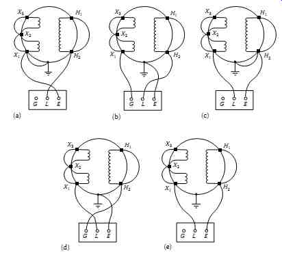
FIG. 4 Test connections for insulation resistance of a single-phase transformer.
Note: In figure (e) reverse the L and E leads to measure from high-winding
to low-winding.
For three-winding transformers, test should be made as follows:
• High to low, tertiary and ground (H-LTG)
• Tertiary to high, low and ground (T-HLG)
• Low to high, tertiary and ground (L-HTG)
• High, low, and tertiary to ground (HLT-G)
• High and tertiary to low and ground (HT-LG)
• Low and tertiary to high and ground (LT-HG)
• High and low to tertiary and ground (HL-TG)
Do not make the megohm test of the transformer winding without the transformer liquid because the values of insulation resistance in air will be much less than in the liquid. Also, do not make the insulation resistance test of the transformer when it is under vacuum because of the possibility of flashover to ground.
The test connections shown in FIG. 5a, c, and e are most frequently used. The test connections in FIG. 5b and d give more precise results.
The readings obtained in the connections in FIG. 5a and b are practically equal to readings in test connections in FIG. 5c and d, respectively.
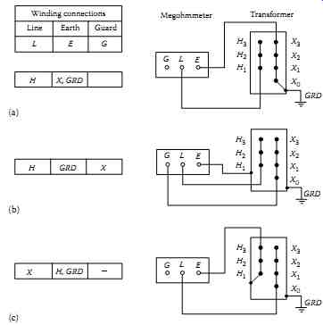
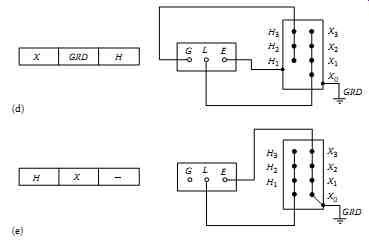
FIG. 5 Test connections for insulation resistance of a three-phase transformer:
(a) connection for high winding to low winding to ground; (b) connection
for high winding to ground and low winding guarded; (c) connection for
low winding to high winding to ground; (d) connection for low winding to
ground and high winding guarded; and (e) connection for high winding to
low winding.
Acceptable insulation resistance values for dry and compound-filled transformers should be comparable to those for Class A rotating machinery, although no standard minimum values are available.
Oil-filled transformers or voltage regulators present a special problem in that the condition of the oil has a marked influence on the insulation resistance of the windings.
In the absence of more reliable data the following formula is suggested:
=
v IR kVA CE
...where...
IR is the minimum 1 min 500 V DC insulation resistance in megohms from winding to ground, with other winding or windings guarded, or from winding to winding with core guarded C is a constant for 20°C measurements E is the voltage rating of winding under test kVA is the rated capacity of winding under test
Values of C at 20°C 60 Hz 25 Hz
Tanked oil-filled type 1.5 1.0
Untanked oil-filled type 30.0 20.0
Dry or compound-filled type 30.0 20.0
This formula is intended for single-phase transformers. If the transformers under test is one of the three-phase type, and the three individual windings are being tested as one, then E is the voltage rating of one of the single-phase windings (phase to phase for delta connected units and phase to neutral or star connected units) kVA is the rated capacity of the completed three-phase winding under test
4.2 Dielectric Absorption Test
The dielectric absorption test is an extension of the transformer winding insulation resistance measurement test. The test consists of applying voltage for 10 min and taking readings of resistance measurements at 1 min intervals.
The resistance values measured during this test are plotted on log-log paper with coordinates of resistance versus time. The slope of the curve for a good insulation system is a straight line increasing with respect to time, whereas a poor insulation system will have a curve that flattens out with respect to time.
There are two tests that are conducted under dielectric absorption test. These are PI and DAR tests, which are discussed in Sections 3.
TABLE 3 Dielectric Test Values for Routine Maintenance of Liquid-Filled Transformers
4.3 DC High-Potential Test
The DC hi-pot test is applied at above the rated voltage of a transformer to evaluate the condition of winding insulation. The DC high-voltage test is not recommended on power transformers above 34.5 kV; instead the AC hi-pot test should be used. Generally, for routine maintenance of transformers, this test is not employed because of the possibility of damage to the winding insulation. However, this test is made for acceptance and after repair of transformers. If the hi-pot test is to be conducted for routine maintenance, the AC test values should not exceed 65% of factory AC test value. The routine maintenance AC voltage value should be converted to an equivalent DC voltage value by multiplying it by 1.6, that is, 1.6 times the AC value for periodic testing (i.e., 1.6 × 65 = 104% of AC factory test value). The DC hi-pot test can be applied as a step-voltage test where readings of leakage current are taken for each step. If excessive leakage current is noticed, voltage can be backed off before further damage takes place. For this reason, the DC hi-pot test is considered to be a nondestructive test. Some companies conduct the AC hi-pot test at rated voltage for 3 min for periodic testing instead of the 65% of factory test voltage. The hi-pot test values for DC voltages are shown in TABLE 3.
The procedure for conducting this test is as follows (refer to FIG. 6a and b for test connections):
Transformer must have passed the insulation resistance test immediately prior to starting this test.
Make sure transformer case and core are grounded.
Disconnect all high-voltage, low-voltage, and neutral connections, low-voltage control systems, fan systems, and meters connected to the transformer winding and core.
Short-circuit with jumpers together all high-voltage bushings and all low-voltage bushings to ground as discussed under "Insulation resistance measurements."
Connect hi-pot test set between high-voltage winding and ground.
Gradually increase test voltage to the desired value. Allow test voltage duration of 1 min, after which gradually decrease voltage to zero.
Remove low-voltage to ground jumper and connect hi-pot test set between low-voltage winding and ground. Also connect the short circuited high-voltage winding to ground. Gradually increase test voltage to desired value. Allow the test voltage duration of 1 min, after which gradually decrease voltage to zero.
If the preceding two tests do not produce breakdowns or failures, the transformer is considered satisfactory and can be energized.
Remove all jumpers and reconnect primary and secondary connections and other system equipment that may have been disconnected.
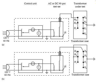
FIG. 6 Transformer high voltage (hi-pot) test connection: (a) high winding
hi-pot test connection and (b) low winding hi-pot test connections.
The following are some cautions and considerations in performing hi-pot tests:
In liquid-filled transformers two insulation systems are in series, that is, solid insulation with oil or synthetic fluid. When AC or DC hi-pot test voltage is applied, the voltage drops are distributed as follows:
=====
Test Voltage | Winding Insulation (Paper-Cellulose) (% Stress Distribution) | Oil Insulation (% Stress Distribution)
AC 25 75
DC 75 25
=====
When using DC hi-pot test voltage on liquid-filled transformers, the solid insulation may be overstressed.
Insulation that may be weakened near the neutral may remain in service due to lower stress under operating conditions. However, when subjected to hi-pot test voltage, it may break down and require immediate repair. The weakened insulation may usually be detected by the measurement at lower voltages.
If a hi-pot test is to be conducted for routine maintenance, consider the following in advance: (1) assume that a breakdown will occur, (2) have replacement or parts on hand, (3) have personnel available to perform work, and (4) is the loss of the transformer until repairs are made beyond the original routine outage?
===