AMAZON multi-meters discounts AMAZON oscilloscope discounts
5. Cables and Accessories
Cable testing is conducted to chart the gradual deterioration over the years, to do acceptance testing after installation, for verification of splices and joints, and for special repair testing. Normally, the maintenance proof tests per formed on cables are at a test voltage of 60% of final factory test voltage.
When the exact construction of cable in an existing installation is not known, it is generally recommended that DC maintenance proof test voltage be based on rated AC circuit voltage using the recommended value for the smallest sized conductor in the rated AC voltage range. The DC voltage tests con ducted on cable are insulation resistance measurement and DC hi-pot test.
The DC hi-pot test can be performed as leakage current versus voltage test, leakage current versus time test, or go, no-go overpotential test.
It is always appropriate to conduct the insulation resistance measurement test first, and if data obtained looks good, then proceed with the DC overpotential test. After DC overpotential test is completed, then perform the insulation resistance again to assure that the cable has not been damaged during the DC overpotential test.
5.1 Insulation Resistance Measurement Test
The insulation resistance is measured using a Megohmmeter (or it can be measured using a portable instrument consisting of a direct voltage source, such as a generator, battery, or rectifier, and a high-range ohmmeter that gives insulation resistance readings in megohms or ohms). This is a nondestructive method of determining the condition of the cable insulation to check contamination due to moisture, dirt, or carbonization. The insulation resistance measurement method does not give the measure of total dielectric strength of cable insulation or weak spots in the cable. Generally, the following voltages can be used for the indicated cable voltage rating.
====
Voltage Rating of Cables (V) Megohmmeter Voltage (V)
>300 500 300-600 500-1,000 2,400-5,000 2,500-5,000 5,000-15,000 5,000-15,000
<15,000 10,000-15,000
====
The following is the general procedure when using a megohmmeter (Megger)* for resistance measurement tests.
Disconnect the cable to be tested from other equipment and circuits to ensure that it is not energized.
Discharge all stored capacitance in the cable by grounding it before testing, as well as after completing tests.
Connect the line terminal of the instrument to the conductor to be tested.
Ground all other conductors together to sheath and to ground.
Connect these to the earth terminal of the test set.
Similarly measure other insulation resistance values between one conductor and all other conductors connected, one conductor to ground and so on. The connections are shown in FIG. 7a through d.
The guard terminal of the megohmmeter can be used to eliminate the effects of surface leakage across exposed insulation at the test end of the cable, or both ends of the cable for leakage to ground.
The insulation resistance measurements should be conducted at regular intervals and records kept for comparison purposes. Keep in mind that, for valid comparison, the readings must be corrected to a base temperature, such as 20°C. A continued downward trend is an indication of insulation deterioration even though the resistance values measured are above the minimum acceptable limit.
Cable and conductor installations present a wide variation of conditions from the point of view of the resistance of the insulation. These conditions result from the many kinds of insulating materials used, the voltage rating or insulation thickness, and the length of the circuit involved in the measurement. Further more, such circuits usually extend over great distances, and may be subjected to wide variations in temperature, which will have an effect on the insulation resistance values obtained. The terminals of cables and conductors will also have an effect on the test values unless they are clean and dry, or guarded.
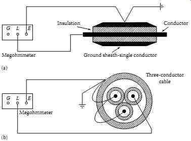
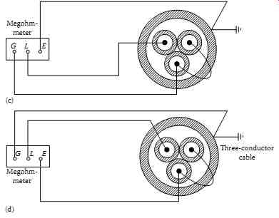
FIG. 7 Cable test connections for insulation resistance measurement:
(a) connection for single-conductor cable, one conductor to ground test;
(b) connection for three-conductor cable, one conductor to other conductors
and sheath to ground; (c) connection for three-conductor cable, one conductor
to sheath and to ground and two conductors guarded; and (d) connection
for three-conductor cable, one conductor to all other conductors without
leakage to ground.
The Insulated Cable Engineers Association (ICEA) gives minimum values of insulation resistance in its specifications for various types of cables and conductors. These minimum values are for new, single-conductor wire and cable after being subjected to an AC high voltage test and based on a DC test potential of 500 V applied for 1 min at a temperature of 60°F.
These standard minimum insulation resistance (IR) values (for single- conductor cable) are based on the following formula:
= 10 IR log D K d
… where…
IR is in megohms per 1000 ft of cable K is a constant for insulating material D is the outside diameter of conductor insulation d is the inside diameter of conductor.
Grade Natural Rubber Synthetic Rubber Code 950 Performance 10,560 2000 Heat resistant 10,560 2000 Ozone resistant 10,000 (butyl) 2000 Kerite 4000 Minimum Values of K at 60°F/1000 ft Insulation Type MW Impregnated paper 2,640 Varnished cambric 2,460 Composite polyethylene 30,000 Polyethylene (thermoplastic) 50,000 Polyvinyl chloride 60°C 500 Polyvinyl chloride 75°C 2,000 Synthetic rubber 2,000 EP insulation 20,000 Cross-linked polyethylene (XLPE) 20,000
The insulation resistance of one conductor of a multiconductor cable to all others and sheath is
= 10 IR log D K d where
D is the diameter over insulation of equivalent single-conductor cable = d + 2c + 2b
d is the diameter of conductor (for sector cables, d equals diameter of round conductor of same cross section) c is the thickness of conductor insulation b is the thickness of jacket insulation
Also, the IEEE standard 690-1984* and 422-1986† recommended an insulation resistance field acceptance limit of [...] where L is the cable length in feet kV is the insulation voltage rating.
5.2 DC Overpotential Testing
In the past, this test has been extensively used for acceptance and maintenance of cables. Recent studies of cable failures indicate that the DC overpotential test may be causing more damage to some cable insulation, such as cross-link polyethylene, than the benefit obtained from such testing (see Section 6 for more details). It can indicate the relative condition of the insulation at voltages above or near operating levels. This test can be used for identification of weakness in the cable insulation and can also be used to break down an incipient fault. A typical DC test set is shown in FIG. 8. Generally, it is not recommended that this test be used for breakdown of incipient faults even though some test engineers use it for this purpose. Therefore, the incipient fault breakdown probability should be anticipated before and during the hi-pot test. The impending cable failure will usually be indicated by sudden changes in the leakage current, and before insulation is damaged, the test can be stopped. The test voltage values for DC hi-pot tests are based upon final factory test voltage, which is determined by the type and thickness of insulation, the size of conductors, the construction of cable, and applicable industry standards. The DC test values corresponding to AC factory proof test voltages specified by the industry standards are usually expressed in terms of the ratio of DC to AC voltage for each insulation system. This ratio is designated as K, which when multiplied by the acceptance test factor of 80% and maintenance factor of 60% yields the conversion factors to obtain the DC test voltages for hi-pot tests. These recommended test voltage conversion factors are shown in TABLE 4. Also, the IEEE standard 400.1-2007 lists the voltage values for conducting hi-pot acceptance and maintenance tests in the field for laminated shielded power cables, which are shown in TABLE 5.
Many factors should be considered in selecting the right voltage for existing cables that are in service. As a general rule, for existing cables, the highest values for maintenance should not exceed 60% of final factory test voltage, and the minimum test value should be not less than the DC equivalent of the AC operating voltage. If the cable cannot be disconnected from all the connected equipment, the test voltage should be reduced to the voltage level of the lowest rated equipment connected. The hi-pot test can be conducted as a step-voltage test as discussed next.
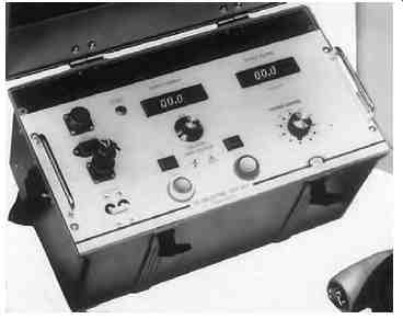
FIG. 8 DC hi-pot test set, 70 kV. (Courtesy of Megger, Inc., Valley Forge,
PA.)
TABLE 4 Conversion Factors for DC Hi-Pot Tests
TABLE 5 Field Test Voltages for Laminated Shielded Cables up to 69 kV System Voltage
5.3 Voltage versus Leakage Current Test (Step-Voltage Test)
In this test, the voltage is raised in equal steps and time is allowed between each step for leakage current to become stable. As explained in Section 1, the current is relatively high as a voltage is applied owing to capacitance charging current and dielectric absorption currents. As time passes, these transient currents become minimum with the steady-state current remaining, which is the actual leakage current and a very small amount of absorption current. At each step of voltage, the leakage current reading is taken before proceeding to the next step. Usually, it is recommended that at least eight equal steps of voltage be used and at least 1-4 min be allowed between each step. The leakage current versus voltage are then plotted as a curve. As long as this plotted curve is linear for each step, the insulation system is in good condition. At some value of step voltage, if the leakage current begins to increase noticeably, an increase in the slope of the curve will be noticed, as shown in FIG. 9. If the test is continued beyond this test voltage, the leakage current will increase even more rapidly and immediate breakdown may occur in the cable insulation. Unless breakdown is desired, the test should be stopped as soon as the increase of slope is noticed in the voltage versus leakage current curve.
FIG. 9 Step-voltage hi-pot test current.
Maximum leakage current allowable for new cables acceptance can be determined from the ICEA formula for minimum allowable insulation resistance discussed earlier. The formula for leakage current then can be written as follows:
… where…
IL is the conduction or leakage current E is the test voltage impressed K is the specific insulation resistance megohms per 1000 ft at 60°F D is the diameter over insulation d is the diameter over conductor.
The typical specific insulation resistance (K) for various commonly used insulations for cables are given under discussion of insulation resistance measurement test.
In order to explain the use of this formula, an example is given below for determining the maximum leakage current allowable for a 15 kV, 500 kcmil cable for an acceptance test.
Example:
A 15 kV cable 500 MCM 220 Mil XLPE insulation conductor OD = 0.813 Class B strand. The circuit is 2500 ft long. Calculate the maximum leakage current at maximum test voltage of 65 kV.
5.4 Leakage Current versus Time Test
When the final test voltage of leakage current versus voltage test is reached, it can be left on for at least 5 min, and the leakage current versus time can be plotted for fixed intervals of time as the leakage current during this step reduces from an initial high value to a steady-state value. A curve for good cables will generally indicate a continuous decrease in leakage current with respect to time or steady-state value without any increase of current during the test. This curve is shown in FIG. 10.
5.5 Go, No-Go Overpotential Test
The hi-pot test can be conducted as a go, no-go overpotential test. In this test the voltage is gradually applied to the specified value. The rate of rise of the test voltage is maintained to provide a steady leakage current until final test voltage is reached. Usually, 1-1.5 min is considered sufficient for reaching the final test voltage. The final test voltage can then be held for 5 min, and if there is no abrupt increase in current sufficient to trip the test set, the test has been successfully passed. This test does not provide a thorough analysis of cable condition, but provides sufficient information as to whether the cable meets a specific high-voltage breakdown strength requirement. This type of test is usually performed after installation and repair, where only cable that can withstand strength verification without a breakdown is to be certified.
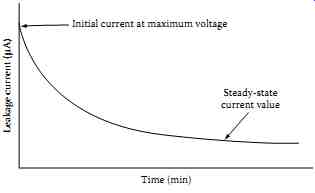
FIG. 10 Leakage current versus time.
5.6 DC Overpotential Test Connections and Procedures
The test connections for this test are similar to test connections shown in FIG. 7a, and for three-conductor cable are similar to those shown in FIG. 7b and c. The test procedures are the following:
Cable to be tested must be de-energized, opened at both ends, and grounded to discharge any electrostatic charge on the cable. Switches, potential transformers, lightning arresters, jumpers from potheads to feeders, fuses, cutouts, and any switchgear should be disconnected. If impossible to disconnect any or some of connected equipment, the test voltage should not exceed the value that could overstress these devices connected to the cable. See FIG. 11 for equipment to be disconnected.
DC test voltage should be applied from phase to ground on each conductor with other conductors, shields, and metallic sheath connected to ground or other conductors guarded with shield and metallic sheath grounded.
Ensure that the hi-pot set main "on-off" switch is in off position and the high-voltage on switch is in the off position with voltage control switch turned to zero position before beginning the tests.
Connect the hi-pot test set safety ground stud to a good electrical ground and make sure the connections are tight. Never operate the DC hi-pot test set without this ground connection. Also connect the shield ground strap of the shielded cable under test to the test set ground stud.
Connect the return line from other conductors not under test to the earth ground terminal or to the guard terminal of the test set as desired. The hi-pot grounding switch should be switched into the appropriate position. Normally, 100 V insulation is required on the return line. Connect the shield and sheath to ground and also to the ground terminal of test set. The guard terminal is provided to bypass the current due to corona and surface leakage around the microammeter so that corona and surface leakage cur rents are not included in the test readings.
Connect one end of the output or line cable to the desired phase of the cable under test, making sure that the connections are tight and without any sharp edges. Where corona currents may be expected owing to the application of high voltages, it is recommended that the connections be taped, covered over with clear plastic bags, or use a corona ring or corona shield. The other end of the output or line cable is connected to the output or line stud of the test set.
Cable used for connecting the hi-pot test set to the cable under test, that is, the line or output cable, should be short and direct and supported along its length so that it is not touching the ground or grounding materials or surfaces. If extension cables are to be used with the output or line cable to reach the cable under test, shielded cable should prefer ably be used for this purpose. The shields of the extension cable and hi-pot cable should be connected with a shield jumper, which should be run away from the splice to prevent leakage. In case of the extension cable being nonshielded, care should be taken to keep the nonshielded wire away from the grounding surfaces as explained previously.
When shielded cable is being tested, it is recommended that the shield be trimmed back about 1 in. for every 10 kV. The shield on the test set end of the cable is connected to ground as explained previously. The shield on the other end of cable can be taped and left hanging without any connections made to it.
Test set now should be plugged into a 115 V, 60 Hz outlet. It is important that the AC supply voltage have good line regulation, because the DC output voltage of the test set depends upon the AC line input voltage. The test voltage kilovolt range should be selected before beginning the test. The power now can be turned on and the test begun either as step-voltage or as a go, no-go test.
After the test is completed, turn the high-voltage switch of the test set to off position. Allow the cable just tested to discharge either through the internal test set discharge circuit or external ground applied to the cable by means of hot stick at 2 kV or below. Do not touch the cable until it is fully discharged.
Connect a ground to the cable that was tested and leave it connected for at least four times the length of the test time or until the cable is connected into the system.
FIG. 11 Hi-pot test for cables and associated equipment, and equipment to be disconnected during tests.
6. Electrical Switchgear and Circuit Breakers
The DC testing of electrical switchgear and circuit breakers involves the following:
- Insulation resistance measurement test
- DC hi-pot test
- Circuit breaker contact resistance test
The insulation resistance measurement test may be conducted on all types of electrical switchgear and circuit breakers using the insulation resistance megohmmeter commonly known as the Megger.
6.1 Insulation Resistance Measurement Test
The insulation resistance test consists of applying voltage (500-15,000 V DC) to the apparatus to determine the megohm value of resistance. This test does not indicate the quality of primary insulation. Several factors should be remembered when performing this test. The first is that this test can indicate low values of insulation resistance because of many parallel paths. The other is that an insulation system having low dielectric strength may indicate high resistance values. In view of this, the test results should only be interpreted for comparative purposes. This does not indicate the quality of the primary insulation system with regard to the dielectric strength to withstand high voltages. The connection diagram for making this test on a power circuit breaker is shown in FIG. 12. The connection diagram for testing the insulation resistance of each branch circuit in a distribution panel is shown in FIG. 13. When performing insulation testing, it is recommended that auxiliary equipment, such as potential transformers and lightning arresters, be isolated from the stationary switchgear.
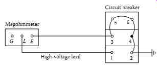
FIG. 12 Typical connection for insulation resistance test of circuit
breaker in open position.
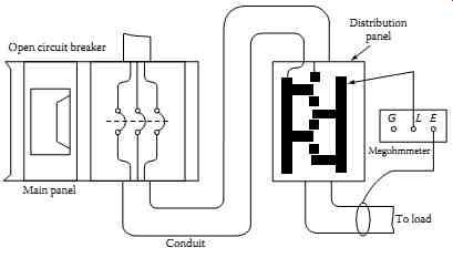
FIG. 13 Insulation resistance testing of branch circuit to ground of
a distribution panel.
Insulation resistance tests are made with the circuit breaker in open and closed position, whereas the insulation test for the switchgear bus is made with one phase to ground at a time, with the other two phases grounded.
The procedure for this test is as follows:
Circuit breaker open: Connect high-voltage lead to pole 1. Ground or guard all other poles. Repeat for poles 2 through 6, in turn, with other poles grounded.
Circuit breaker closed: • Connect high-voltage lead to pole 1, with either pole of phase 2 and 3 grounded. Repeat for phases 2 and 3 with other phases grounded.
Stationary gear (buses): • Connect high-voltage lead to phase 1 with phases 2 and 3 grounded or guarded. Repeat the same for phases 2 and 3 with other phases grounded. Repeat this test for checking the insulation resistance between phase 1 to 2, phase 2 to 3, and phase 3 to 1.
In the case of outdoor oil circuit breaker bushings, experience has shown that any bushing, with its assembled associated insulating members, should, for reliable operation, have an insulation resistance value above 10,000 M-Ohm at 20°C. This assumes that the oil within the tank is in good condition, that the breaker is separated from its external connections to other equipment, and that the porcelain weather shield is guarded. This means that each component such as the stripped bushing itself, cross-member, lift rod, lower arcing shield, etc. should have an insulation resistance in excess of that value.
Any components that are superficially clean and dry and have values less than 10,000 M-ohm are usually deteriorated internally, by the presence of moisture or carbonized paths, to such an extent that they are not reliable for good service unless reconditioned. This is particularly so when operating under surge conditions such as during lightning disturbances. In the case of the stripped bushing itself, the lower stem and upper weather shield must be either perfectly clean or guarded before it is condemned as unreliable because of an insulation resistance value less than 10,000 M-Ohm.
Since bushings and other associated members have very high insulation resistance values normally, a megohmmeter insulation tester having a range of at least 10,000 M-Ohm is necessary to test such equipment. Megohmmeter instruments having ranges up to 50,000 MO will permit observation of deteriorating trends in bushings before they reach the questionable value of 10,000 M-Ohm.
6.2 DC High-Potential Test
The hi-pot testing of switchgear involves testing of the circuit breakers and switchgear buses separately. This is a major test and determines the condition of the insulation of the switchgear assembly. The DC hi-pot test is not preferred for testing AC switchgear because the application of DC voltage does not pro duce similar stress in the insulation system as is produced under operating conditions. Moreover, the DC hi-pot test produces corona and tracking owing to concentration of stress at sharp edges or endpoints of buses. The corona and tracking are more pronounced in older equipment, and it is therefore recommended that DC hi-pot testing be avoided on such equipment.
The test procedures for DC hi-pot testing are similar to those of AC hi-pot testing. If DC hi-pot testing is to be performed, the DC voltage test values shown in TABLE 6 are recommended for various voltage-class equipment.
The hi-pot test should be conducted under conditions similar to those of commercial testing. The switchgear should be wiped, cleaned, and restored to good condition before the hi-pot test is conducted. Temperature and humidity readings should be recorded and the test reading corrected when conducting DC tests.
====
TABLE 6 DC Hi-Pot Maintenance
Test Values
Rating Operating Voltage (V) | 1 Min DC Test Voltage
=====
6.3 Circuit Breaker Contact Resistance Measurement Test
Stationary and moving contacts are built from materials that provide good resistance to arcing. However, if contacts are not maintained on a regular basis, resistance due to repeated arcing builds up resulting in the contacts ability to carry current. Excessive corrosion of contacts is detrimental to the breaker performance. One way to check contacts is to apply DC current and measure the contact resistance or voltage drop across the closed contacts.
The breaker contact resistance should be measured from bushing terminal to bushing terminal with the breaker in closed position. It is recommended that for medium and high voltages the resistance test be made with a micro ohmmeter having at least 100 A DC output. The use of a higher current value gives more reliable results than using lower current values. The resistance value is usually measured in micro-ohms (µΩ).
===