AMAZON multi-meters discounts AMAZON oscilloscope discounts
7. Motors and Generators
The electrical insulation system is the most prominent part of motors and generators that needs periodic maintenance and testing. The insulation system of machines is subjected to varying degrees of mechanical, thermal, and electrical stresses. The reliability of a machine depends upon the integrity of its insulation system. Therefore, a preventive maintenance program should include an effective testing program, along with visual inspection and routine maintenance, to evaluate the insulating system.
The insulating parts found in motors and generators consist of stator windings, field windings, winding support, collector lead and ring, stator core, and others. The maintenance and testing program should be planned to detect and provide data on deteriorating factors to which motors and generators are subjected. The following DC tests can be conducted for the purposes of preventive maintenance to assess the condition of insulation systems of motors and generators.
7.1 Insulation Resistance Test
This test is conducted with voltages from 500 to 5000 V and provides information on the condition of machine insulation. A clean, dry insulation system has very low leakage as compared to a wet and contaminated insulation system.
This test does not check the high-voltage strength of the insulation system, but does provide information whether the insulation system has high leakage resistance or not. This test is commonly made before the high-voltage test to identify insulation contamination or faults. This test can be made on all or parts of the machine circuit to ground. The following procedures are given for making this test on field winding, stator windings, and individual stator windings. Typical synchronous motor or generator connections are shown in FIG. 14.
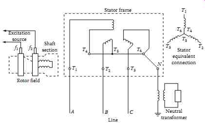
FIG. 14 Typical in-service connection for synchronous machines.
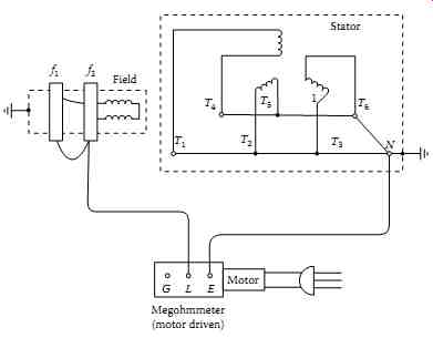 FIG. 15 Test connections for field winding insulation resistance measurement.
7.1.1 Field-Winding Test Procedures
The test connection is shown in FIG. 15 and the procedures are as follows:
1. Lift brushes on the rotor
2. Disconnect neutral terminal from neutral device or ground
3. Ground all stator terminals, stator frames, and rotor shaft
4. Ground f1 and f2 for 30 min before conducting test to completely discharge winding
5. Disconnect ground from f1 and f2, connect test instrument (megohm meter) ground terminal to ground, and test voltage lead to f1 and f2
6. Perform one of the following:
a. Ten minute test to determine PI
b. One minute test to determine DAR
c. One minute test to determine insulation resistance value
7.1.2 Overall Stator (Armature Windings) Test
The following procedures are given for conducting this test, and the connection diagram is shown in FIG. 16.
1. Check that stator frame and rotor shafts are grounded
2. Ground rotor terminals f1 and f2
3. Connect ground terminal of instrument to ground and connect test voltage lead to all motor terminals that are connected together
4. Remove ground connection from stator winding
5. Perform the following:
a. Ten minute test, that is, PI test
b. One minute test, that is, DAR test
c. One minute test, that is, insulation resistance value
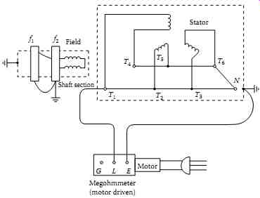
FIG. 16 Test connection for overall stator winding test.
7.1.3 Overall System Test for the Motor or Generator
The overall system test includes generator neutral, transformer, all stator windings, isolated phase bus, and low side windings of generator step-up transformer. This test is performed as a screening test after an abnormal occurrence on the machine. If the reading is satisfactory, no further tests are made. If the reading is questionable or lower, the machine terminals are disconnected and further isolation performed to locate the source of the trouble. Similarly, it may be desirable to test a motor including its cables to pre vent disconnection of motor terminals unnecessarily. The connection diagrams are shown in FIG. 17a and b for generator system and a motor, respectively.
7.1.4 Individual Stator Winding Test
The following procedures are given for conducting this test, and the test connection diagram is shown in FIG. 18.
• Ground stator terminals for 30 min
• Disconnect all stator terminals
• T1 through T6 and leave neutral terminal disconnected
Test • T1-T4 winding with T2-T5, T3-T6, and rotor grounded
Test • T2-T5 winding with T3-T6, T1-T4, and rotor grounded
Test • T3-T6 winding with T1-T4, T2-T5, and rotor grounded
The connections for the four insulation resistance measurement tests are summarized in TABLE 7.
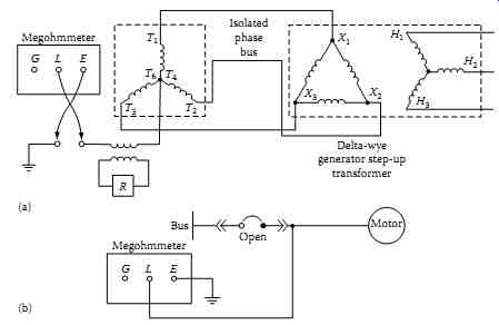
FIG. 17 Test connection for an overall system for generator or motor:
(a) generator system and (b) motor.
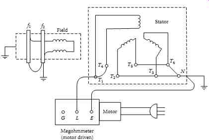
FIG. 18 Connection diagram for individual stator winding test.
TABLE 7 Insulation Resistance Test Connections
The IEEE standard 43-2000, "Recommended Practices for Testing Insulation Resistance of Rotating Machinery," provides information on making and interpreting insulation resistance measurements for rotating machinery.
It reviews the factors that affect or change insulation resistance characteristics, outlines and recommends uniform methods for making tests, and presents formulas for the calculation of approximate minimum insulation resistance values for various types of AC and DC rotating machinery. The guide states:
The recommended minimum insulation resistance Rm for AC and DC machine armature windings and for field windings of AC and DC machines can be determined by:
=+ m kV 1 R
… where…
Rm = recommended minimum insulation resistance in megohms at 40°C of the entire machine winding kV = rated machine terminal to terminal potential, in kilovolts In applications where the machine is vital, it has been considered good practice to initiate reconditioning should the insulation resistance, having been well above the minimum value, drop appreciably to near that level.
The PI value of 2 or more is acceptable for insulating systems such as varnish-impregnated windings and asphalt windings, whereas thermoplastic insulation systems have a higher value than 2. A PI value of less than 1.0 indicates deterioration of the windings, which should be investigated. A very high PI value (above 5) indicates dried out, brittle windings such as is the case in very old machines.
7.2 DC Overpotential Test
The DC overpotential test is conducted on motors and generators to assess the insulation dielectric strength. This test can be made during routine maintenance or after repairs have been made on the machine. Either all or parts of the machine can be tested to ground to ensure that the insulation system has sufficiently high dielectric strength for safe operation.
As a general rule, the AC voltage used for the factory proof testing of the machine windings of motors or generators is based upon the rated operating voltages of the machine. A commonly used rule for establishing factory test values for stator windings is two times rated voltage (E) plus 1000 V. For DC field winding it is 10 times the excitation voltage. To convert these value to DC overpotential test values, the multiplying factor is 1.7. The recommended DC acceptance test voltage is 75% of the equipment AC voltage used for the factory proof test, whereas the recommended DC maintenance test voltage is 65% of the factory proof test value. These values can be represented by the following equations:
[...]
The values mentioned may be varied depending upon the type and size of the machine. The standard duration of the DC overpotential test is usually 1-5 min for most electrical machines but may be varied depending upon the type and size. The reader is urged to consult IEEE standard 95-2007, Guide for Insulation Testing of AC Electric Machinery (2300 V and above) with High Direct Voltage, for further information on this subject. To obtain meaningful results, the DC maintenance test voltage should not be below 50% of the equipment AC factory test value.
7.3 Voltage versus Leakage Current Test (Step-Voltage Test)
The DC overpotential test is a controlled test; that is, the increase in applied voltage is controlled by monitoring the leakage current to identify any impending failures of the winding insulation with the intention of stopping the test before the breakdown occurs. This test is commonly known as the step-voltage test, and the test connection diagram is shown in FIG. 19.
This test procedure may be described as follows:
First voltage step is usually one-third of the calculated test voltage, which is applied to the machine. Readings are taken at 1 min intervals up to a maximum of 10 min.
Next step is to increase the test voltage in about-equal 1000 V steps and record the leakage current value for each step. Allow sufficient time between each step for leakage current to become stable.
At each step, plot the values of leakage current on the vertical axis versus the applied test voltage on the horizontal axis. For a good insulation system, the curve generated by the readings will be smooth with rising slope. Any sudden changes in curve characteristics are indications of impending winding failure.
Take steps to eliminate the possibility of excessive leakage due to ionization in order to measure the true leakage current.
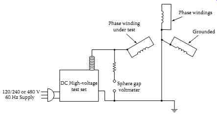
FIG. 19 DC overpotential test connections for an AC machine armature
(stator).
7.4 Leakage Current versus Time Test
This test can be made in lieu of the voltage versus leakage current test.
In this test, the point is to separate the absorption current from the total leakage current. In this test, reasonable time is allowed during each step of applied test voltage to allow the absorption current to disappear before readings are taken. To completely eliminate the absorption current, many hours of test time will be necessary. Therefore, a reasonable time interval is taken to be a 10 min waiting period during each step of applied voltage. The IEEE standard 95 describes this test in its appendix; which may be summarized as follows:
Apply an initial voltage of about 30% on the machine winding and hold for 10 min. The readings are taken at regular intervals and are plotted on a log-log graph, with leakage current on the vertical axis and time on the horizontal axis.
A curve is generated by the points plotted on the graph. This curve is used to calculate the conduction component (leakage current) of measured current. The total current readings at time intervals of, say, 1, 3, and 10 min are used and substituted into the following formula for calculation of the conduction component (C):
… where i1.0 is the 1 min total current i3.0 is the 3 min total current i10.0 is the 10 min total current.
The value of C as calculated from this formula is subtracted from the total current at 1 and 10 min interval readings. The difference of the current readings gives the current due to absorption. These values are used to calculate the absorption ration N, which is equal to…
… where ia1.0 is the absorption current at 1 min ia10.0 is the absorption current at 10 min The absorption ratio N is then used to select the time intervals from a precalculated schedule, as shown in IEEE standard 95.
The test now may be carried out for the remaining steps of test voltage using the precalculated values of time steps. The readings of leakage current versus voltage are taken at the end of each step.
A new curve may be generated by plotting the leakage current on the vertical axis and voltage on the horizontal axis. The curve obtained should be a straight line with rising slope if the rate of increase of conduction current component is linear. Moisture in the insulation system will produce a continuous upward slope, whereas void ionization will exhibit minor breaks in the slope of the curve. However, a sharp break in the curve will usually indicate an impending failure.
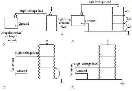
FIG. 20 Lightning arrester test connections: (a) basic test connection
for lightning arrester; (b) to test top arrester in stack; (c) to test
middle arrester; and (d) to test bottom arrester.
8. Lightning Arresters
The maintenance tests that may be made on lightning arresters with DC voltage is insulation resistance measurement. Following are the generalized maintenance procedures for lightning arresters for conducting the insulation resistance test:
Apply (usually) 2500 V to line terminal with base grounded with an insulation resistance tester as shown in FIG. 20. Readings are characteristic of each type of arrester. Some may be as high as 10,000 M-Ohm; others may be much lower, such as 500 M-Ohm. The evaluation should be based on comparing readings with previous test results or test values of similar equipment.
Lightning arresters may also be tested using DC high potential voltage. The DC voltage should be 1.7 times rated voltage of lightning arresters.
Field testing of station-class arresters may be accomplished during normal operation by measuring the leakage current through the arrester. Because of the high impedance to ground characteristics of arresters, an increase in leakage current above normal usually indicates a defective arrester. The evaluation of test data should be based upon comparing the leakage current values with previous values or measurements obtained on similar units or comparative values of the three single-pole arresters in the single installation.
It is also recommended that oscillographic measurements be made, if possible, because this will provide the most complete information, which allows for the best comparison.
9. Capacitors
Several different tests may be performed on power-factor correction capacitors to determine their suitability for service. From these, users may select tests that they deem practical and necessary. Factors that influence the selection of tests may be the type of banks, such as substation banks or distribution lines, electrical arrangements, failure rate experiences, and others.
NEMA Standards Publication CP1-1977, Section 6.06, "Field Test on Capacitor Units," listed the two options: (1) checking new capacitor units before placing in service and (2) after they have been placed in service. For historical perspective, the requirements for checking the capacitor units before placing them in service were the following:
9.1 Tests to Check the Condition of New Capacitor Units before Placing in Service
Perform the following tests:
Terminal-to-terminal AC or DC high-voltage test at 75% of factory routine (production) test voltage.
Short-circuited terminal-to-case (two-terminal units only) perform impulse and DC high-voltage test according to voltage rating table given in the old standard. This section also states, "Experience has shown that these tests are not necessary on all capacitor units." The most current standard, CP1-2000, lists only one option for checking the new capacitor units after they are placed in service. These requirements are the following.
9.2 Tests to Check the Condition of a Capacitor Unit after It Has Been in Service
Serviceability of a capacitor unit may be determined by one or more of the following tests in case of trouble or after exposure to possible damage:
Capacitance measurements by current measurement at known voltage and rated frequency, or by a low voltage capacitance meter. These tests will generally indicate a short-circuited capacitor or open-circuited capacitor.
Line-to-line internal discharge resistor may be checked with a suitable bridge or calculated from DC voltage and current readings.
Line-to-case insulation resistance measurements may be made to determine the condition of the insulating terminals and dielectric insulation to case. The resistance measured should be not less than 1000 M-Ohm. This test is not applicable to single bushing capacitors. Measuring the line to-case power factor or dielectric loss is another means of determining the condition of the line insulating terminals and insulation to case.
Measurable characteristics of properly applied and installed capacitors, which are hermetically sealed, are not expected to change with time. Therefore, periodic testing may not be necessary. However, operating conditions may change, resulting in damage and short life; hence, periodic inspection and check of such operating conditions as outlined previously in this section are highly desirable.
Liquid tightness at 50°C may be used if manufacturer's limit is not available.
NEMA standard CP1-2000 provides options that enable a user to develop a test program suitable to its needs. The discharge resistor measurements and calculations from current measurements at low voltage can be compared readily with manufacturers' values and serve as a reference for future comparison.
Current measurements at low voltage have proven value for two other purposes:
Detection of short-circuited sections in a capacitor
Predetermination and correction of unbalanced current in split-wye banks during installation
The test programs for substation and distribution lines have proved to be realistic during installation and in service situations. TABLE 8 references NEMA recommended test values in the older CP1-1977 and the latest CP1 2000 standards.
TABLE 8 Capacitor AC to DC High-Voltage Field Tests
10. Evaluation of Test Data Readings
Insulation resistance measurements, coupled with other information, can serve as a guide to determine what actions to take on electrical apparatus or cables. The choices are as follows:
- Place or restore the circuit to service until the next scheduled inspection.
- Restore the circuit to service now, but plan to perform indicated repairs as soon as possible.
- Leave out of service until repairs have been made.
What factors should be considered to determine whether insulation is good or bad?
Rule of thumb: Minimum acceptable value of insulation to place equipment in service is 1 M-Ohm per rated kilovolt plus 1 M-Ohm. This is based upon experience rather than the characteristics of insulation.
The insulation resistance should never be less than 1 M-Ohm for all equipment.
Manufacturers' information when available.
Comparison with values obtained at acceptance or installation.
Comparison with values from previous routine tests.
Comparison with values of several similar units.
What physical factors may influence the readings?
Contamination including dirt, moisture, acids, and salts.
Contamination at terminal connection or at an end point can cause a low reading, and the true reading of a winding or cable will be unknown.
Readings should be compared at a common temperature base, for example, 20°C. Different insulating materials have different tempera ture correction tables, which are available in manufacturers' literature.
TABLE 9 Minimum Acceptable Insulation
Resistance at 20°C for Safely Energizing Electric Power Equipment
10.1 Acceptance Criteria for Rating Insulation
The minimum acceptable insulation resistance for safe energization of power equipment of each nominal voltage class is listed in TABLE 9. Values below these minimums indicate moisture, substantial thermal or chemical degradation, contamination, or physical damage. Equipment whose insulation resistance is less than the appropriate minimum is susceptible to disruptive failure and must not be energized for safety as well as economic reasons.
TABLE 15 lists the insulation resistance values that are considered acceptable for healthy insulation. By examining the data given in Tables 2.9 and 2.15, the difference should be obvious to the reader between what is considered a good value versus the absolute minimum value when evaluating the health of an insulation system.
An insulation resistance above the minimum in the table indicates only that the severely degraded conditions mentioned above do not exist and that the equipment may be energized safely. This does not necessarily mean that the insulation has acceptable dielectric strength, or that it is free of deterioration. A clean, dry insulation system in excellent condition should have a resistance several orders of magnitude larger than the mini mum required for safe energization. For instance, the resistance of good 600 V class insulation is typically in the 100-1000 MO range.
In reality, the measured insulation resistance is of little significance on a one-time basis as long as it is well above the acceptance level. However, a long-term trend toward lower resistance strongly indicates progressive deterioration, which should be investigated and corrected.
To allow meaningful trending, the influence of irrelevant factors must be eliminated from the series of insulation resistance readings. The primary such factor is temperature. The measured resistance of a solid insulation system can change by as much two orders of magnitude as its temperature varies from the bottom to the top of the rated operating temperature range of the equipment. To eliminate this effect, tests whose results will be used for trending either should always be performed at essentially the same insulation temperature, or the results converted to a common temperature base.
Insulation testing and test trending procedures for equipment should be written accordingly.
In practice, the first alternative implies either testing the insulation when it is at nearly normal operating temperature, that is, as soon as possible after a period of normal, stable loading, or after the insulation has cooled to an ambient temperature, which is above the dew point and remains reasonably stable from test to test. In the second, more common approach, the resistances measured at varying temperatures are converted to a common standard temperature of 20°C using tables of empirically based correction factors given in the literature. Temperature coefficients of resistance vary greatly with the chemical composition of the insulation, so different corrections are required for different insulation systems. The equipment manufacturers' literature is the best source of temperature correction information.
Humidity also affects the measured insulation resistance, but not nearly as much as temperature if the insulation system is reasonably clean.
In fact, large variations in insulation resistance with ambient humidity, in the absence of other explanations, indicate a possibility of contamination, which should be investigated. It is not normally necessary to correct for humidity effects.
Tables 10 through 15 provide examples of rating insulation for various apparatus and equipment as to whether it is good, bad, or needs further investigation.
TABLE 10 Example of Evaluating 15 kV Cable Readings
TABLE 11 Example for a Lightning Arrester Might Be as Follows
TABLE 12 Example for a Generator Might Be as Follows
TABLE 13 Example of Insulation Resistance Values for Transformers
TABLE 14 Example of DAR and PI for Motors and Generators
TABLE 15 Representative Insulation Resistance Values for Electrical Apparatus
11 Precautions When Making DC Tests
DC overpotential test can be conducted any time an equipment is taken out of service for a few hours; however, it is preferred that the test be planned in conjunction with a periodic dismantled inspection of the equipment. This will allow time to investigate the cause of unsatisfactory test results and make necessary repairs with a mini mum of interference to normal production.
Equipment should be taken off the line sufficiently in advance of the test to permit it to cool below 40°C (104°F). Testing at ambient temperature is preferred.
Insulation of windings should be relatively clean and dry. If excessive foreign matter is present, the windings should be cleaned prior to conducting the test. Any cleaning solvent used should be allowed to evaporate thoroughly so that the surface of the insulation is dry; otherwise, false leakage current readings may result.
Where it is possible to do so, especially with large rotating machines, phase connections should be opened in order to test each phase separately, phase to phase and phase to ground. All windings not under test should be short-circuited and grounded to the machine frame.
As a safety precaution, before any DC voltage tests are conducted, a ground should be applied to the unit or cable to be tested.
Allow the DC voltage to discharge sufficiently, especially in cables after tests have been concluded. A common rule of thumb is that the discharge time should be four times the charge time.
All components require de-energizing and solid grounding before being tested. Check with a reliable voltage indicator that responds to alternating current (AC) and DC voltage before testing to ensure all equipment is deenergized.
All cable termination ends as well as all connecting leads of components being tested should be guarded from accidental contact by barriers, enclosures, or a watchman at all points. The cable ends should be separated from all elements not being tested by distances at least 0.1 in/kV of test potential for voltages up to 100 kV and at least 0.2 in/kV for higher test voltages.
Breakdown may generate traveling waves into the cable that can be high enough to cause degradation or breakdown of the insulation being tested. Installation of suitable rod gaps should be considered according to IEEE Std 4 for DC voltages to provide protection.
A damping resistor may be installed to reduce oscillations and reflection voltages into the insulation being tested.
===