AMAZON multi-meters discounts AMAZON oscilloscope discounts
1. Introduction
This section covers the power factor (PF) and dissipation factor (DF) tests that are ordinarily conducted in the field for acceptance (start-up) and routine field (maintenance) testing of insulation of electrical equipment and apparatus. The PF and DF tests are conducted using the 60 Hz power frequency voltages, therefore these tests may be referred to as alternating current (AC) voltage tests. The purpose of conducting these tests is to identify if the equipment has been installed properly, determine if corrective maintenance and repair is needed, and/or track the gradual deterioration of the equipment over its life. The question might be asked, why conduct these tests? The answer is obvious because the equipment to be tested is normally energized with 60 Hz AC voltage, therefore testing with the same type of voltage that the equipment sees in service provides the best information on the condition of that equipment. By applying an AC voltage test potential across a series of insulations (insulation system), the voltage drop across each layer of insulation and the resulting measured losses can be equated to true operating conditions. The voltage drop is proportional to the dielectric constant of the insulation layers. There are other AC voltage tests that may be performed along with PF and DF tests. The AC voltage tests can be classified into the categories as listed below:
1. PF and DF
2. AC high potential tests
3. Very low frequency (VLF)
4. AC series resonant
5. Induced frequency
6. Partial discharge (PD)
7. Impulse tests
The AC tests may be classified as destructive and nondestructive tests. The PF and DF tests are considered nondestructive since the test voltages used in performing these tests do not exceed line-to-neutral voltages of the equipment being tested. The basic principle of the nondestructive testing is the detection of a change in the measurable characteristics of an insulation that can be associated with the effects of contaminants and destructive agents without over- stressing the insulation. The AC high potential, VLF, and AC series resonant tests may be classified as destructive since the test voltages associated with these tests are higher than normal operating voltages which may overstress the insulation. The effect of repeated high voltage (HV) tests on insulation are cumulative and therefore thoughtful consideration should be given on the benefits of these tests for routine field and maintenance testing, except for special investigations or for acceptance testing. The induced frequency, PD, and impulse tests are primarily conducted at the factory during manufacturing of electrical apparatus and equipment. However, for special investigations these tests may be performed in the field but will require special test equipment and setup. The AC high potential, AC series resonant, VLF, PD, induced frequency, and impulse tests are covered in other sections under respective equipment category. This section is exclusively devoted to PF and DF testing methods.
2. PF and DF Test Methods
2.1 General
The PF insulation tests were used in the laboratory since the early 1900s by cable manufactures, and in the field for testing bushing since 1929. The DF is based on the Schering bridge which was developed also in the early 1900s to evaluate insulation by separating the capacitive and real components of the charging current. Today, the PF and DF tests are considered to be synonymous because they both refer to the AC dielectric loss test. PF and DF are but two of the several measurable characteristics that can be obtained from an AC dielectric loss test used for evaluating the condition of the insulation system. Both of these tests are effective in locating weaknesses in the electrical insulation and hazard in the power apparatus before impending failure.
PF and DF tests are not go-no-go tests, and can measure dielectric loss, capacitance, and AC resistance of the insulation of the electrical apparatus. These tests can measure the presence of bad insulation even when there may be a layer of good insulation in series with the bad insulation. These tests pro vide information on the overall condition of the insulation in terms of a ratio (i.e., PF or DF value of insulation) that is independent of the volume of the insulation being tested. Moreover, they provide assessment of the insulation under normal frequency (60 Hz) operating conditions which is not time dependent like the direct current (DC) voltage tests. The PF and DF tests do not overstress the insulation and can determine if the insulation is slowly degrading by comparison with previous year's test results, or with test results of similar equipment.
2.2 Principles of PF/DF Testing

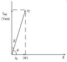
FIG. 1
Vector relationship of voltage, resistive, and capacitive current (IT, total
current; Icap, capacitive current; IR, resistive current; q, PF angle;
and d, dissipation angle).
The PF/DF tests measure insulation capacitance, AC dielectric losses, and the ratio of the measured quantities. When insulation is energized with an AC voltage, the insulation draws a charging current. This charging cur rent comprises of two components called capacitive current and resistive current. The capacitive current leads the applied test voltage by 90°, whereas the resistive current is in phase with the voltage as shown in FIG. 1. The capacitive current is directly proportional to the dielectric constant, area, and voltage and inversely proportional to the thickness of the insulation under test. The capacitive current may calculated by the following formula:
The above equation may be written as:
… where …
E is the test voltage
C = e0e r(A/d)
e0 is the dielectric constant of vacuum (0.08854 × 10⁻¹² F/cm)
e r is the dielectric constant of the insulation
A is the area (cm^2) d is the thickness of insulation f is the frequency
Changes in the capacitive current indicate degradation in the insulation, such as wetness or shorted layers, or change in the geometry of the insulation.
The resistive current supplies the energy lost due to dielectric losses such as carbon tracking, volumetric leakage, surface conduction, and corona.
Dielectric losses due to water contamination or carbon tracking or other forms of deterioration increase by the square of the voltage, where as dielectric losses due to corona increase exponentially as the voltage increases.
PF/DF testing is sensitive enough to detect a deteriorated moisture problem in the insulation compared to an insulation resistance test.
Although there are several manufacturers of PF/DF test equipment, this text describes PF test methods and procedures based on the PF test equipment of Megger Incorporated (originally Megger Instruments), Valley Forge, Pennsylvania and Doble Engineering Company, Watertown, Massachusetts.
The PF methods, theory, and principles discussed in this text are also applicable to the PF test equipment of other manufactures. It should be noted that in the electrical industry, especially in the utility transmission and distribution (T&D) arena, the PF test may be referred to as Doble test* because of the use of the Doble test sets when performing PF tests. The terms PF test and Doble test are one and the same.
2.3 Factors That Influence PF Measurements
The PF measurement is a searching diagnostic tool for evaluating insulation condition. It is a fundamental concept that changes in insulation quality result in measurable changes in some of the basic electrical characteristics of the insulation, such as capacitance, dielectric loss, or PF. Therefore, by measuring these electrical characteristics over time, changes in the integrity of the insulation can be assessed. Unfortunately, PF tests cannot always be con ducted under the desired or same conditions because the equipment may be located outdoors or the environment may be different from test to test. There are two environmental variables which cannot be controlled easily; they are temperature and humidity. Also, depending on the cleanliness of the insulation and relative humidity, surface leakage current can also have an effect on the PF measurements. The electrical characteristics of most insulation materials vary with temperature. In order to compare the results of routine PF tests measurements taken at different temperatures for the same equipment, it is necessary to normalize the results to a common base temperature. It is a recommended practice to convert the measured PF values to a common base temperature of 20°C. When equipment is tested near freezing temperatures where a large correction factor may cause the resultant PF to be unacceptably high, then the equipment should be retested at a higher temperature before the equipment is condemned. Similarly, when high PF results are encountered at high temperature, the equipment should be retested after it has been al lowed to cool down. Also, PF tests should not be performed for detection of presence of moisture in the insulation when the temperatures are much below freezing, because the ice has a resistivity of approximately 144 times that of water.
Although, the temperature correction factors have been developed for correcting the measured PF results to a common base temperature, no such factors are available for humidity effects because of other variable effects.
One of variables that affects the insulation measurement is surface leakage, which is dependent upon the moisture and the cleanliness of the surface of the specimen under test. When making PF tests, the effects of surface leakage (due to humidity, dirt, etc.) should be recognized and addressed accordingly.
The effects of surface leakage current may be minimized by cleaning and drying external surfaces to reduce the losses, or using guard collars to divert the surface leakage current from the measuring circuit, or using the combination of the two approaches. Some cases may be handled quite easily with no thought or effort as to control of surface leakage, while others may require an extra effort to produce good results. It should also be recognized that there will be times when it will be best to postpone tests until another day. Refer to Section 7 for further discussion of variables affecting PF measurements.
The PF test results may be converted to the reference temperature of 20°C (68°F) using the conversion factors given in the test manual. The procedure for normalizing the test results to 20°C consists of (1) determine the test specimen PF, (2) measure the test specimen temperature, (3) obtain the appropriate correction factor from the table corresponding to the specimen temperature, and (4) multiply the calculated PF value with the correction factor.
3. Description of the PF Test Equipment
3.1 PF and DF Test Set
There are several manufacturers of the PF/DF test equipment. However, there are two main suppliers of PF/DF instruments in the United States, and they are Megger Incorporated, Valley Forge, Pennsylvania and Doble Engineering, Watertown, Massachusetts. The test sets listed below are in use for performing PF/DF tests on electric power system apparatus.
Megger Incorporated, Valley Forge, PA | Voltage
Model CB-100, Cat. No. 810130 28 V Semi-automatic, Cat. No. 670025 2.5 kV Semi-automatic, Cat. No. 670065 12 kV Extended semi-automatic, Cat. No. 670070 12 kV Model Delta-2000, Cat. No. 672001 12 kV Model Delta-3000, Cat. No. 673001 12 kV
Doble Engineering, Watertown, MA | Voltage (kV)
MEU 2.5 M2H-MCM-fully automated 12 Type M4000/4100 12
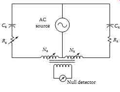
This section briefly describes the Megger DF test equipment, its theory, and its operation for performing PF tests. The description of theory and operation for all types listed are essentially the same. A transformer ratio-arm bridge circuit is used as shown in the simplified diagram of FIG. 2.
The circuit consists of a standard reference capacitor (CS) and the insulation under test (CX). A special multiwinding transformer is the characteristic feature of the circuit. A voltage is applied to both CS and CX. The ratio arms, NS and NX are adjusted to balance capacitive current, and the variable resistor (RS) is adjusted to balance resistive current. The null indicator is used to determine when the bridge circuit is balanced. The values of NS and NX are used to determine capacitance and the value of RS correlates to power ( dissipation) factor of the test insulation.

FIG. 2 Simplified circuit diagram of Megger DF test set (transformer
ratio-arm bridge.)

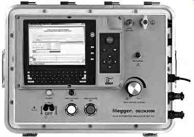
FIG. 3 The Delta-3000 test set. (Courtesy of Megger, Inc., Valley Forge,
PA.)
Model CB-100 is a low voltage ( LV) bridge which is manually balanced for both capacitance and DF, but it is direct reading. The semiautomatic models require manual balancing for capacitance, but they provide a direct digital readout of DF. Model Delta-3000 is automatic balancing for both capacitance and PF, and can also display DF directly ( FIG. 3).
Some of the major features of the Delta-3000 test set are listed below:
- Completely self-contained test set including 0 to 12 kV power supply, standard capacitor, instrumentation, test leads, and printer
- It is simple to operate, providing automatic balancing and digital display for voltage, current, dielectric loss (in watts), capacitance, and PF
- Readings are adjusted to equivalent values of 10 or 2.5 kV
- Readings may be recorded on a thermal printer for hardcopy, and/or on a removable data key for download at a later time to a standard PC
- It achieves high accuracy under severe electrostatic and electromagnetic interference conditions, such as encountered in HV substations
- Safety features include two hand-operated interlock switches, open ground detection circuitry and zero voltage initiation of tests
- Built-in diagnostic and calibration self-check
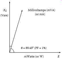
The formulas used for calculating the PF or DF are illustrated by using an example ( FIG. 4) with an insulation of PF = 1.0%. The value of PF is given by the cosine of the q angle, or the equation can be written as:
… dielectric losses PF cos charging volt-amps watts (W) volt-amps (VA) 0.01 (1%)
Also, PF is approximately equal to DF when PF and DF <10.0%, that is
=d= cos tan cotan qq
== cos(89.43) tan(0.57) 0.01(1%)
Therefore, PF test results are comparable with DF test results up to 10.0%.

FIG. 4 Vector diagram of an insulation specimen of PF of 1%.
3.2 General Instructions for the Operation of the Megger Test Set
1. Assemble the test set in accordance with the operating instruction manual.
2. Connect ground lead from the test set to a station ground.
Caution: PF tests are performed only on de-energized and isolated apparatus. Verify the equipment is cleared before attempting to connect leads.
3. Prepare the specimen for testing. This may include removing external connections, shorting winding terminals, etc.
4. Connect test leads: first to the test set, then to the apparatus to be tested following the instructions in the operating manual.
5. Check operation of safety and ground interlocks if supplied on the test set.
6. Select the proper test configuration for the insulation to be measured.
7. Initiate voltage output from the test set. Raise output voltage to the desired level.
8. Continue operation of the test set to obtain test readings, following the specific instructions in the operating manual.
a. For manual test sets, balance the bridge for capacitance and PF.
b. For semiautomatic test sets, balance the bridge for capacitance.
c. For automatic test sets, select measure to initiate automatic balancing.
9. Reduce voltage to zero, or lowest setting and deinitiate voltage output.
10. Record all values as provided by the test set: test voltage, current, watts-loss, capacitance, and PF.
For specific operating instructions for any Megger test set, the reader is advised to follow the instructions given in the appropriate test set operating manual.
3.3 Doble PF Test Set
This section briefly describes the Doble Engineering Company test equipment, its theory, and operation for performing PF tests. The description of theory and operation is based on the MEU test set, but the theory and operation of the other test sets is the same for all test sets as manufactured by Doble Engineering. The type MEU test set has special measuring circuit in which the total current (IT) of the insulation specimen is measured. Then a balancing network is switched into the measuring circuit and the capacitive component (IC) of the specimen current is balanced out. The in-phase component (IR) of the specimen current is then measured.
The formulas used for calculating the PF or DF are illustrated by using the example of FIG. 4 with an insulation of PF of 1.0%. The value of PF is given by the cosine q, or the equation can be written as given below for the 2.5 kV MEU and 10 kV M2H test set:
Doble MEU test set:
× %PF = (mW 100)/(mVA)
× %PF = [(dielectric losses in milliwatts)/(milli-volt-amps)] 100 Doble M2H test set:
% PF = (W 10)/(mA) ×
× %PF = [(dielectric losses in watts)/(charging milliamps)] 10
3.4 Operation of Doble PF Test Set
The following is a set of general instructions which describe the procedure for operating the Doble test sets:
1. Assemble test set in accordance with the instruction book.
2. Check the ground and the HV connections and safety switches.
3. Connect specimen for the desired test. Raise test voltage to desired level.
4. Adjust the meter reading to full scale. The test set is ready to use and to record the test current and dielectric loss for the specimen.
5. Measure total charging current as the product of the meter reading and a multiplier within the proper range.
6. Specimen loss is measured by turning the milliwatts-adjust which cancels the capacitive reactance. When the capacitive reactance is cancelled the meter will be at minimum reading. This meter reading and the proper multiplier provides the milliwatt for the dielectric loss in the insulation.
7. The capacitance of the specimen is automatically obtained as a product of capacitance multiplier and capacitance dial reading at mini mum milliwatts balance.
8. The product of the meter reading and the meter multiplier is the milliwatts loss of the specimen.
9. The power supply polarity is reversed to cancel the effect of electro static interference. The average of the two milliwatts results is calculated as the specimen milliwatts loss.
10. The test set has shielding to minimize the effect of electrostatic interference, as well as electromagnetic interference. For cases where high interference is encountered, a special interference cancellation circuit is available with the 10 kV test sets from Doble Engineering. The more advanced design of the Doble M4000 test set does not require interference cancellation circuit.