AMAZON multi-meters discounts AMAZON oscilloscope discounts
4. Basic Test Connections (Test Modes) for PF Testing
To help understand the PF test operation, it is convenient to consider the relative connections of the AC source, the bridge circuit, and the test specimen with respect to ground and the LV lead(s). FIG. 5a through c shows basic test configurations that simplify testing on complicated insulation systems inside HV apparatus.
4.1 Grounded-Specimen Test Mode
In grounded-specimen test (GST) mode, all current between the AC source and ground (through CX) is measured by the bridge ( FIG. 5a). GST is used when one terminal of the insulation to be measured is permanently connected to ground, such as a bushing flange, transformer tank, or grounded apparatus frame. GST mode also connects the LV lead(s) directly to ground. This enables the lead(s) to be used to ground a specimen terminal that is not normally grounded.
4.2 GST Mode with Guard (GST-G)
In Doble test sets this connection is referred to as guard-specimen test mode.
In this mode, all current between the AC source and ground (through CX) is measured by the bridge ( FIG. 5b). The LV lead(s) may be connected to the test circuit guard. Any current present on the LV lead(s) during the test are bypassed directly to the AC source return, and are eliminated from the measurement. GST-G mode is used to isolate an individual section of insulation and test it without measuring other connected insulation.
4.3 Ungrounded-Specimen Test Mode
In ungrounded-specimen test (UST) Mode, only current between the AC source and the LV lead (through CX)is measured ( FIG. 5c). Any current flowing to a grounded terminal is bypassed directly to the AC source return, and is eliminated from the measurement. UST mode is only used to measure insulation between two ungrounded terminals of the apparatus. In UST mode, ground is considered guard since grounded terminals are not measured. UST mode is used to isolate an individual section of insulation and test it without measuring other connected insulation.
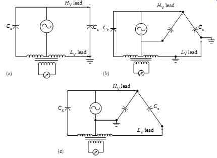
FIG. 5 Test circuit modes of the PF test set (typical). (a) GST; (b)
GST-G connection; and (c) UST connection.
5. Safety Cautions with PF Testing
Safety cannot be overstressed when working with and around HV. Companies that work with HV should and do have precise rules for working in and around the various types of HV apparatus and their associated lines and conductors. The purpose of these instructions is to reemphasize some generally acknowledged rules to be observed, and to outline some specific rules which must be adhered to strictly when making tests with PF test equipment.
All PF tests are performed with the apparatus to be tested completely de-energized and isolated from the power system. In addition, the apparatus housing or tank must be properly grounded. There is no substitute for a visual check to ensure that the apparatus terminals are isolated from the power source.
For example, each pole of a three phase disconnect switch should be checked individually because there have been cases where one pole of a gang-operated disconnect failed to open with the others. Strictly observe all company rules and procedures for tagging and isolating the apparatus.
It is possible for the apparatus insulation to retain some charge after being switched out of service. Also, since field testing usually involves work in the vicinity of energized lines and apparatus, it is possible for relatively HVs to be induced in supposedly de-energized apparatus; this is particularly true when long lengths of bus are left connected to the de-energized apparatus.
Trapped charges and induced voltages may not, by themselves, be sufficient to cause serious injury. Even relatively low energy charges are potentially hazardous in that an unexpected shock may cause a person to jump or fall from the apparatus. Therefore, safety grounds should be applied to all apparatus terminals before doing any work on them, and before connecting and disconnecting the PF test leads.
The PF test set should be located where the operator will have an unobstructed view of the apparatus under test and of various personnel assisting in the tests. Consideration should also be taken to place the equipment such that proper clearance is maintained between the test set and apparatus; in particular, it should be recognized that damaged or defective apparatus may fail during test.
Before proceeding with a test, the operator should discuss with his assistants the general plan for conducting the tests, voltages applied, precautions to be observed, and proper use of the safety devices.
PF field test sets are equipped with ground-relay that prevents test voltage being applied until the following preliminary conditions have been established:
1. A heavy-duty safety (station ground) has been applied to the ground receptacle of the test set.
2. The test case has been grounded through the 120 V supply cord.
3. The voltage control is at the fully counterclockwise zero voltage stop.
After the test set is properly grounded, the remaining test leads and HV test cable are plugged into their receptacles. Do not connect test leads to the apparatus terminals unless the leads are already connected to the PF test set.
The PF test set require two-person operation, and therefore two safety switches (deadman switches) are provided with the test set. These switches are of the spring-release type for quick action. With either switch off, all volt age to the HV test cable is removed. The test person operating the PF test set has one of the safety switch, known as the local operator switch; the safety supervisor or the person assisting in PF testing should hold the second safety switch, known as the extension safety switch. The safety supervisor or the assisting person should be in position to observe all terminals of the apparatus under test. If this is not possible, then the out-of-sight terminals should be roped off with caution labels appropriately placed, and a person posted in the vicinity to ensure safety.
Each time the test equipment is set up, prior to making the first test both safety switch operators should jointly verify the correct operation of both switches.
It is apparent that the operator of the second safety switch should not close the switch until all personnel are safely in the clear; personnel should not be permitted to remain atop the apparatus as it is being tested. Also, if unauthorized personnel should enter the area, or if some other undesirable situation should occur, the extension-safety switch operator should release the switch immediately and then notify the test set operator.
Both safety switches must be used at all times. Never short circuit them and do not use fixed mechanical locking means for depressing the switch button. The switch must be manually operated at all times.
The HV test cable used with PF test equipment is a double shielded cable in which the HV is exposed only at the outboard pothead tip. Nevertheless, it is recommended that the HV test cable not be handled while it is energized.
The cable may be suspended or tied off in such a manner as to avoid handing.
The test set operator and assistant should follow a uniform system of visual and oral signals in order to prevent confusion when conducting the tests.
After the tests are completed all test leads should be removed from the equipment terminals and brought down to the ground before they are disconnected from the test set. The heavy-duty test set ground is the last lead to be removed from the test set. "Remember, safety, first, last, always."