AMAZON multi-meters discounts AMAZON oscilloscope discounts
6. PF Testing of Electrical Apparatus Insulation
PF testing is normally used for acceptance testing, preventing maintenance, and post maintenance insulation assessment, and for condition trending.
The test voltage used for PF testing should be sufficient to detect any latent weaknesses in the insulation, but since the test is intended to be nondestructive, the voltage should not exceed normal line-to-neutral or line-to-ground operating voltage of the apparatus under test. Below, the PF testing of various electrical apparatus and equipment is discussed.
6.1 Transformers
Power and distribution transformers may be either single-phase or three phase and may be either dry-type, or oil or synthetic-liquid filled. Transformers may be installed indoors or outdoors depending upon application. The PF test as applied to transformers is the most comprehensive test for detecting insulation degradation, usually caused by moisture, carbonization, and other forms of contamination. Depending on the type, size, and voltage rating of transformer, the PF test may be performed as an overall transformer PF test, or on individual components of the transformer to localize the dielectric circuit for effective analysis of the test results; that is deterioration in the solid winding, bushing, and liquid insulation can be localized by separate tests on these components. Generally, it is common practice to perform PF tests of the bushing and the solid winding together on medium-voltage transformers that have solid porcelain-type bushings. On HV transformers with condenser-type bushings, the PF tests are performed on the individual bushings by the UST method. On all other bushings, hot-collar tests are performed by the GST method.
The types of transformers considered for the purposes of PF testing are
1. Two-winding transformers
2. Three-winding transformers
3. Autotransformers
4. Potential transformers (PTs)
When performing PF tests on transformers, the below listed conditions should be observed:
1. Transformer is de-energized and completely isolated from the power source.
2. Transformer housing is properly grounded.
3. All bushing of HV and LV winding, including the neutral are shorted to make them into an equivalent HV and LV bushings. Neutrals must be ungrounded.
4. Transformers equipped with load-tap-changers should be set to some position off neutral, and this position should be noted on the test data sheet.
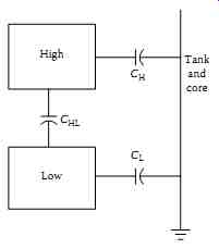
FIG. 6 Insulation circuit of two winding transformer.
TABLE 1 PF Tests for Two-Winding Transformers
6.1.1 Two-Winding Transformers
In a three-phase or a single-phase two-winding transformer, the transformer winding insulation system comprises of three insulation system; that is, CH HV winding insulation, CL LV winding insulation, and CHL high-to-low winding insulation. The three insulation systems are shown in FIG. 6.
When performing PF tests, the HV bushing of the three phase units are shorted together to make them into an equivalent single bushing. Similarly, the LV bushing of three phase unit are also shorted together to make them into an equivalent bushing. Four PF tests of the windings are made as shown in TABLE 1. As shown in the TABLE 1, results of test 1 minus test 2, and test 3 minus test 4 are calculated to validate that the PF test have been made correctly.
Calculated results of TABLE 1: test 1 minus test 2
1. Subtract charging current of test 2 from test 1
2. Subtract watt loss of test 2 from test 1
3. Then calculate the PF, that is
+-= H HL H HL [][] CC C C
Test 3 minus test 4
1. Subtract charging current of test 4 from test 3
2. Subtract watt loss of test 4 from test 3
3. Then calculate the PF, that is
[...]
The calculated value of CHL from the above calculation should be same. If it is not then there is either an error in the test results or the calculated results.
The test connection arrangements for each of the four tests listed in the TABLE 1 are described below in FIG. 7a through d.
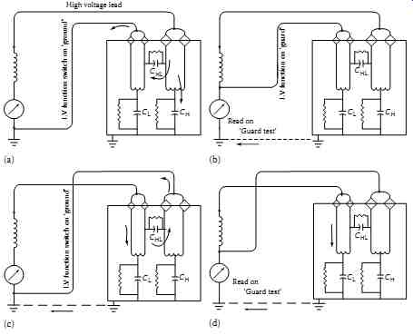
FIG. 7 Measurements of (a) high winding and high-to-low winding insulation;
(b) high winding insulation; (c) low winding and high-to-low winding insulation;
and (d) low winding insulation.
Test #1: Grounded test mode (GST) HV winding is energized LV winding is
grounded The meter reads CH plus CHL Test #2: Guard test mode (GST) HV
winding is energized LV winding is guarded The meter reads CH Test #3:
Grounded test mode (GST) LV winding is energized HV winding is grounded
The meter reads CL plus CHL Test #4: (Guard test mode) LV winding is energized
HV winding is guarded The meter reads CL
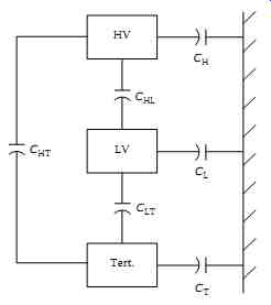
FIG. 8 Insulation circuit of three-winding transformer.
TABLE 2 PF Tests for Three-Winding Transformers
6.1.2 Three-Winding Transformers
The equivalent circuit of a three-winding transformer insulation system is shown in FIG. 8. The insulation system in a three-winding transformer is similar to the two-winding transformer except that there is an additional winding in the transformer. The standard test procedure for a three-winding transformers is given in TABLE This test technique for three-winding transformers is an extension of the two-winding transformers.
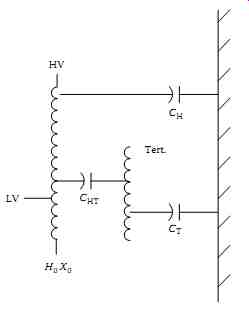
FIG. 9 Insulation circuit of an autotransformer.
TABLE 3 PF Tests for an Autotransformers
6.1.3 Autotransformers
The equivalent circuit of an autotransformer insulation system is shown in FIG. 9. The PF tests that are conducted on an autotransformer are shown in TABLE 3. For test purposes, an autotransformer is considered the same as the two winding transformer with the exceptions that the HV is a combination of HV and LV winding which cannot be separated physically. To short circuit the HV winding on a three-phase unit all seven bushings are shorted together when performing PF tests; H1, H2, H3, X1, X2, X3, and H0, X0.
6.1.4 PTs
PTs are used on HV systems for metering and relaying applications. Because of LV rating of the PTs, the PF tests are routinely performed only on the primary winding of the PTs. Care should be exercised when performing PF tests on PTs to ensure that the PT is completely and effectively isolated from the power source before any tests are conducted. The test connections for conducting PF tests are shown in FIG. 10. The tests that are conducted on PTs are shown in TABLE 4.
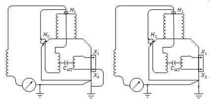
FIG. 10 PF test connections for a single-phase PT.
TABLE 4 PF Tests for PT
6.2 Transformer Bushing
Transformer bushing may be classified into condenser and non-condenser type. The condenser-type bushing consists of oil-impregnated paper insulation or resin-bonded paper insulation with interspersed conducting (condenser) layers. The non-condenser-type bushing consists of solid core, alternate layers of solid and liquid insulation, homogeneous insulating materials, or gas-filled insulation. Bushing may be further classified as having capacitance taps or PF taps. Bushing rated at 69 kV and above have capacitance taps where as bushing 23 to 69 kV have PF test taps. A condenser-type bushing is usually used on transformers above 50 kV. The condenser-type bushing is made up of equal capacitance layers (concentric capacitors) between the center conductor and ground flange. These concentric capacitors provide equal voltage steps; that is a uniform voltage gradient. As shown in FIG. 11, the condenser-type bushing consists of 10 equal capacitance layers and each layer has a capacitance of 1 pico-farad (pf). Therefore the total capacitance (C) is equal to 0.1 pf. For example, if one capacitance layer breaks down then the capacitance of the bushing would be one-ninth or 0.11 pf; or an increase in bushing capacitance of 0.01 pf, or 10% increase. FIG. 11 also shows the various insulations associated with the condenser-type bushing. The main insulation C1 is the insulation from conductor to the tap electrode or shield layer; the tap insulation C2 is between tap electrode and ground or flange; and C3 is the overall insulation to ground of the upper and lower porcelain.
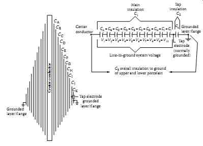
FIG. 11 Equivalent diagram of a condenser-type bushing.
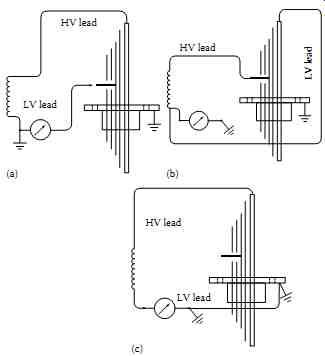
FIG. 12 Measurements of (a) main insulation (C1); (b) tap insulation
(C2); and (c) insulation of a bushing without taps.
PF tests on bushing are usually performed by energizing the bushing conductor and measuring the test current and loss for the insulation system between the conductor and grounded flange. Many modern bushings have capacitance taps or PF test taps. Test on bushings with taps can separately determine the core insulation (C1) from the tap insulation (C2). The various insulation systems of the bushing with taps are shown in FIG. 12.
The test connections for performing PF test on bushing are given below.
It should be noted that all bushing except the bushing under test are shorted and grounded.
Test No. 1: This test measures the C1 insulation of the bushing (see FIG. 12a).
1. Remove capacitance (or PF tap) tap cover from the bushing under test and make connections as shown.
2. Put LV switch of PF test in UST mode.
3. Measure charging current and watt loss.
4. Calculate PF and capacitance; correct to 20°C.
5. Compare results to manufacturers PF and capacitance on nameplate.
6. Capacitance should be ±10% of nameplate and PF depends on manufacturer (<1%).
Test No. 2: This test measures the C2 insulation of the bushing (see FIG. 12b).
1. Remove capacitance (or PF tap) tap cover from the bushing under test and make connections as shown.
2. Put LV switch of PF test in guard mode.
3. Guard C1 insulation as shown in the diagram.
4. Measure charging current and watt loss.
5. Calculate PF and capacitance; correct to 20°C.
6. Compare results to manufacturer's PF and capacitance on nameplate.
7. Capacitance should be ±10% of nameplate and PF depends on manufacturer (<1%).
8. Limit test voltages to 500 V for bushing less than 69 kV.
9. Limit test voltages to 5000 V for bushing greater than 115 kV.
10. Limit test voltages to 2000 V for Westinghouse "O"-plus bushing.
Test No. 3: This test measures the C1 and C2 insulation of the bushing (optional test).
1. Remove capacitance (or PF tap) tap cover from the bushing under test and make connections of the HV lead as shown in FIG. 12b.
2. Put LV switch of PF test in ground mode, i.e., C1 is not guarded out as was the case in Test No. 2, i.e., the low voltage lead is connected to ground side of the meter.
3. Limit test voltages as shown in Test No. 2.
4. This test measures C1 and C2, but C1 is very small compared to C2, therefore measures C2.
Test No. 4: This test measures the C3 insulation of the bushing (optional test).
1. Remove capacitance (or PF tap) tap cover from the bushing under test and make connections as shown in FIG. 12a.
2. Put LV switch of PF test in guard mode to guard out C2.
3. Measure charging current and watt loss.
4. Calculate PF and capacitance; correct to 20 o C.
Test No. 5: This test measures the insulation of the bushing without capacitance or PF taps, or bushing not installed in equipment, i.e., spares (see FIG. 12c).
1. Put LV switch of PF test in GST mode and make connections as shown in FIG. 12c.
2. Measure IT and watts loss; rate insulation on basis of watt loss.
3. Limit should be less than 0.1 W.
6.2.1 Hot-Collar Tests of Noncondenser-Type Bushings
The hot-collar tests may be performed on compound-type, porcelain dry-type bushing, oil-filled bushings, and cable pot heads. The collar is energized by the test voltage (thus the term hot collar), while the center conductor is grounded. It is well-established fact that the compound and dry type bushing fail from leaks that develop in the top end of the bushing allowing moisture to enter the bushing chamber. As a result, leakage paths are established which lead to bushing failure. By applying collar test in the upper region of the bushing, moisture, or deterioration can be detected in the early stages.
The collar tests are also useful in detecting low levels of oil or compound in bushing and pot heads. The collar can be made of conductive rubber or metallic foil, braid or wire. When performing collar tests, care should be used to ensure that the collar makes intimate contact with the surface of the bushing or pothead. Hot-collar tests may be made as single collar tests or multiple collar tests as shown in FIG. 13a through d. A single hot-collar test consists of a measurement between an externally applied collar and the bushing, while the center conductor is grounded (GST mode). In this test mode ( FIG. 13a), all currents passing between the energized collar and ground are measured.
In the UST mode ( FIG. 13b), current between the energized collar and the center conductor are measured including the surface leakage currents flowing over the upper portion of the bushing whereas the surface leakage cur rents flowing in the lower portion of the bushing (grounded flange mounting) are not measured. In the guard mode ( FIG. 13c), the currents between the energized collar and the center conductor are measured and the surface leak age currents flowing over the upper and lower portion of the bushing are guarded, whereas in FIG. 13d, the surface leakage current over the upper portion of the bushing only are guarded.
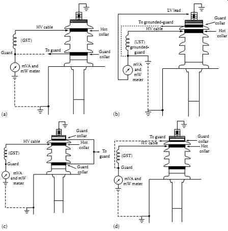
FIG. 13 Hot-collar test of bushings in (a) GST mode; (b) UST mode; (c)
guard mode, guard above and below; and (d) guard mode, guard above.
6.3 Transformer Excitation Current Test
Transformer excitation current test is another test that can be performed with the PF test equipment. Excitation current is also known as the no-load or magnetizing current of the transformer. In this test, voltage is applied to the primary windings one at time with all other windings left open. The excitation current of a transformer is the current the transformer draws when voltage is applied to its primary terminals with the secondary terminal open.
The excitation current test, when used in routine preventive maintenance or field acceptance testing of transformers, provides means of detection for winding problems, such as short-circuited or open turns, poor joints or contacts, core problems, etc.
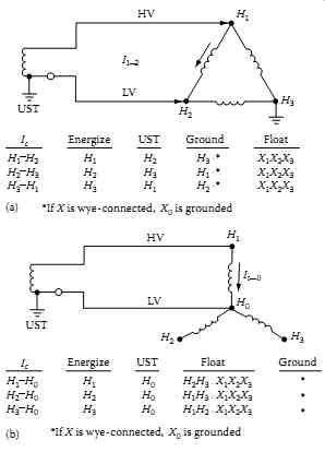
FIG. 14 Excitation current test method for (a) wye-connected winding
and (b) Delta-connected winding.
The excitation current test is conducted on each phase winding at a time, that is only one winding is under test with the other winding including the secondary winding are floating. When performing this test, the bushings are not shorted together like they are when conducting the PF tests. The test is performed by applying voltage to one end of the transformer winding and connecting the other end with the LV switch of the PF test set in the UST position.
FIG. 14b shows the single phase energization of H1-H0 of a three-phase wye-connected unit. Three measurements are routinely made (H1-H0, H2-H0, and H3-H0) at voltages generally below rated voltage-not exceeding 2.5 or 10 kV depending upon the PF test set equipment. The LV winding, not shown in this figure, is isolated from its source or load and is left floating during the test. The neutral is left grounded, as is in normal service. The exciting current flows in the core such that two high and one low readings are obtained because the middle leg carries a lower amount of current compared to the two outer core legs. This is because when the middle winding H2-H0 is energized, the current flows only in the middle leg and does not involve the joints and yokes of the core, where as when the H1-H0 and H3-H0 windings are energized, the current flow path involves the respective core leg, two joints and two yokes which gives the higher current.
FIG. 13a shows the single phase energization of H1-H2 of a three-phase Delta-connected transformer. Similar to the wye-connected transformer, three readings are routinely made (H1-H2, H2-H3, and H3-H1) and measurement recorded. In this case, the readings of the exciting current are two low and one high reading because of the current flow path in the core. When H1-H2 winding is energized, the current flows in two core legs, four joints, and four yokes thereby giving a high current. Whereas when H2-H3 and H3-H1 windings are energized, the current path involves two core legs, four joints, and two yokes which give a lower current measurement. When evaluating excitation current test results, it is important to remember that the excitation current measurements should have a pattern of two high and one low, or two low and one high reading depending upon the transformer winding connections.
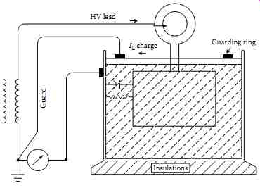
FIG. 15 Power factor testing of the insulating liquid.
6.4 Transformer Insulating Oils and Fluids
In order to perform PF tests on transformer oils and fluids with the PF test set, a special cell is provided with the test set. The cell is essentially a capacitor which utilizes the insulating liquid as the dielectric. In order to make this test, a sample of the insulating fluid or oil should be obtained from the transformer by opening the sample valve. Remember to flush approximately one-quart of oil or fluid into a bucket to clean any contaminants from the valve housing. Once this is done, then fill cell with oil sample to just above the raised center of the cell to prevent any sparking due to insufficient amount of oil. This cell holds approximately one-quart of fluid. Make connections of the cell as shown in FIG. 15. The test voltage should be 2.5 or 10 kV depending upon the PF test being used. The test voltage should be raised gradually to the desired level. Readings should be taken, and PF value calculated in the normal manner as is done with the solid insulation tests. Take the temperature of the oil or fluid sample immediately after the test completion. Correct the measured PF to 20°C.
6.5 Lightning Arrestors
Most station and intermediate class arrestors are of unit design, where gap and valve elements are enclosed in a single porcelain housing. These employ a series of gap elements with shunting resistors to shield the gaps and to pro vide uniform voltage distribution across the individual gaps and unit. The arrestor has electrical characteristics, such as AC grading current and dielectric loss, which is measurable. Failure of the arrestors can be attributed to several causes, such as damaged, defective or contaminated units, lightning strokes, long-duration surges due to switching and misapplication. Arrestors have low capacitance and experience has shown that the measurement of dielectric loss is effective in detecting defective, contaminated, and deteriorated arrestors. The dielectric loss indicates the mechanical condition and insulating qualities of the arrestor. Arrestors may consists of single units or assemblies (stacked units) depending on application for a given equipment rating. Arrestors are tested as single units to assure that the arrestor's mechanical and insulation integrity is intact so that it can perform its intended function. Before conducting any tests on arrestors, the line connected to the arrestor should be first de-energized and grounded, then disconnected from the arrestors. Arrestor assemblies consisting of single units are first disconnected from the bus and then tested by the GST method as shown in FIG. 16a. Assemblies consisting of two or more units are tested using a combination of GST method and UST method as shown in FIG. 16b. In case of assemblies of three or more units per phase, it is only necessary to de-energize the line and ground the top of the arrestor stack. In this case the bus need not be disconnected from the arrestor stack.
Since the arresters exhibit nonlinear characteristics, the losses may vary depending upon the applied test voltages. In order to compare dielectric losses for the various units, all tests must be performed at prescribed voltages. The TABLE 5 gives the recommended voltages for testing lightning arresters.
6.6 Circuit Breakers
Circuit breakers vary from very simple designs to large and very elaborate designs. The main purpose of the circuit breaker is not only to carry and interrupt load currents but also to interrupt abnormally high currents that flow during fault conditions. Circuit breakers are designed to conform to the particular characteristics of the power system to which they are applied. The voltage of a given power system determines the insulating requirements needed for the circuit breakers used in the system. Therefore many different principles and insulating mediums are used in the construction of the circuit breakers. The principal insulation mediums used for circuit breakers are air, oil, vacuum, and sulfur hexafluoride (SF6) gas. The PF tests for circuit breakers are described in Sections 6.6.1 through 6.6.3.
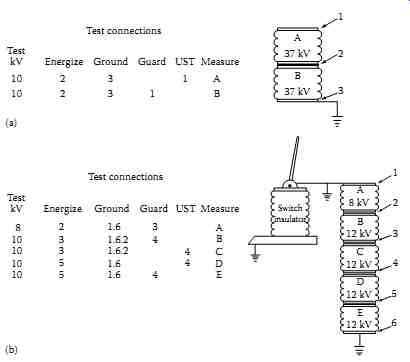
FIG. 16 PF measurements of (a) two-stack arrestors and (b) multistacked
arrestors.
TABLE 5 Recommended Test Voltages for Lightning Arresters
Arrestor Unit (kV) Test Potential (kV)
3.0 2.5 4.5 4.0 6.0 5.0 7.5 7.0 9.0 7.5 12 and greater 10.0
6.6.1 Medium-Voltage Circuit Breakers
The circuit breakers covered in this group are air magnetic, air blast, and vacuum-type circuit breakers usually applied at voltages 1000 V and above.
The air magnetic and air blast breakers use arc chutes that are installed over the breaker contacts for arc interruption where as vacuum breaker contact assembly is housed in a vacuum bottle. A circuit breaker is a gang operated device, that is the three-phase contacts are opened and closed simultaneously. The breaker three-phase bushing are numbered 1 through 6 with phase A numbered as 1 and 2, phase B numbered as 3 and 4, and phase C numbered as 5 and 6. The PF tests are performed on the circuit breaker as shown in TABLE 6 with the circuit breaker in open position.
In order to eliminate the influence of the arc chutes on the bushings and other ground insulation, it is recommended to make tests 1 through 6 with the arc chutes raised or removed. The breaker frame must be properly grounded in order to obtained good test data. Since circuit breakers have very small capacitance, PF is not calculated, instead evaluation of the results is based on current and dielectric loss measurements. The test connections for test 1 through 6 are shown in FIG. 17a and for tests 7 through 9 in FIG. 17b.
6.6.2 Oil Circuit Breakers (OCBs)
An OCB consists of gang-operated three single-pole switches whose contacts are immersed in oil. Most units have one grounded tank per phase although some designs may have all three phases housed in a single tank. Major components of a circuit breaker are:
Two bushing per phase mounted in an oil-filled grounded tank
A contact assembly (interrupter) mounted on the bottom terminal of each bushing
An insulating operating rod to open and close breaker contacts
An insulated guide assembly to keep the operating rod in proper alignment
Tank containing a volume of insulating oil to provide arc quenching
Some breakers may have tank liners, shunt resistors across the interrupters, and other auxiliary components. The primary object of the insulation test on the OCB is to determine the condition of the above-listed OCB components, particularly bushings which are most vulnerable especially at higher volt ages. Nine overall tests are routinely performed on a three-phase OCB, three overall tests per phase as listed in TABLE 7. The open circuit breaker tests measure the insulation of bushing, oil, interrupter, lift rod guide, and tank liner. The closed circuit breaker tests measure both bushings, oil, both interrupters, lift rod, and tank liner. The test connections for the open breaker and closed breaker are shown in FIG. 18a and b, respectively.
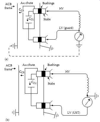
FIG. 17 (a) Open circuit breaker tests and (b) closed circuit breaker
tests.
TABLE 7 PF Tests Procedure for OCB
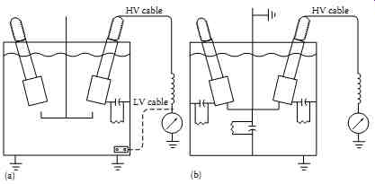
FIG. 18 (a) OCB open breaker tests and (b) OCB closed breaker tests.
TABLE 8 Guide for Investigating Abnormal TLI of OCB
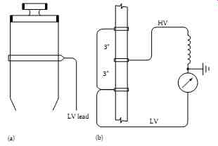
FIG. 19 (a) PF tests of OCB interrupter assembly and (b) dielectric loss
test of OCB lift rod assembly.
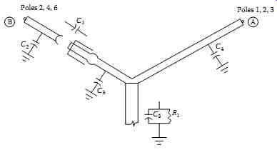
FIG. 20 The capacitances of SF6 breaker.
The difference between open circuit breaker and closed circuit breaker tests is that in the closed circuit breaker test a larger dielectric field is established. The watts loss of a closed breaker test is different from the sum of the two open breaker watts loss because during the closed breaker test, the cross head is energized thus placing the lift rod in a stronger dielectric field. Also, the average dielectric field within the tank is increased during the closed breaker test. Since the difference between a closed OCB test is different than the sum of the two open OCB tests, then any differences must be due to losses in the auxiliary insulations which are not stressed the same for both conditions. The amount of such differences can be used to evaluate the condition of the auxiliary insulation, and is referred to as the tank loss index (TLI) test. TLI test is defined as the difference in watts loss between closed breaker test minus the sum of the two open breaker tests, or TLI can be writ ten as the following:
=- TLI Closed breaker loss sum of open breaker losses
The polarity sign of the loss measurement for the TLI should be noted in order to indicate the type of problem with the circuit breaker. TABLE 8 gives the guidance for investigating abnormal TLI values for the OCB. When it is indicated that auxiliary insulation of the OCB requires further investigation then the interrupter and lift rod can be tested as shown on FIG. 19a and b.
With tank down, or oil removed from the OCB, perform the following test on the interrupter assembly.
UST Test-OCB Interrupter Assembly:
1. Energize HV bushing
2. LV lead on hot-collar strap around interrupter
3. Measure current and watt loss; calculate PF UST Test-Lift Rod Assembly:
1. Use 10 kV test set
2. Stress insulation to 40 kV per foot
3. Measure current and watt loss; calculate PF
6.7 SF6 Breaker
This type of breaker contains inert, nontoxic, and odorless gas known as SF6.
The SF6 gas is kept under pressure from 45 to 240 lb/in.
2 and extinguishes the arc rapidly. These types of breakers are usually used at higher voltages although some limited use of this gas is found in medium voltage switchgear and circuit breakers in the United States. The capacitances of a single pole unit SF6 breaker are shown in FIG. 20. The routine PF test conducted on this type of breaker are shown in TABLE 9.
TABLE 9 PF Tests Procedure for SF Breaker (All Tests with Breaker Open)
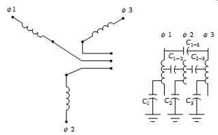
FIG. 21 Insulation systems of a machine.
6.8 Rotating Machinery
Rotating machinery includes machines such as motors, generators, synchro nous condensers, and other machines. Although PF test can be performed on any size machine, they are routinely conducted on machines rated at 2.4 kV and higher voltages. Because of higher voltage and large charging currents (large capacitance) of relatively large machines, the 2500 V PF test set is not often used for conducting the PF tests. However, if the capacitance of the machine is within the charging capacity of the 2500 V test set, then the PF test may be conducted with this test set. It is a normal practice to use the 10 kV PF test set to perform PF tests on HV machines. Some manufacturer's of PF test set supply a special resonator (inductive unit) with the 10 kV test sets for testing very large capacitance machines which normally could not be tested otherwise.
A three-phase machine insulation is complex since it is made up of several insulation systems, but for test purposes the machine insulation can be considered to have two insulation systems. These two insulations are phase to-ground insulation known as ground-wall insulation, and interphase insulation which is known as end-turn insulation. These two insulations are represented as capacitances and are shown below, and in FIG. 21.
Machine Insulation Systems
C1-3, Ground-wall insulation, phase-to-ground
C1-2, End-turn insulation, phase-to-phase
C2-3, End-turn insulation, phase-to-phase
C1-3, End-turn insulation, phase-to-phase
The PF tests of machine insulation provide indication of the overall general condition of the insulation; that is the presence of contamination, moisture, corona (ionization), or other forms of contamination. The applied test voltage for the PF tests usually can be used up to the machine phase-to-neutral rating.
It is recommended that two sets of tests be performed on the machine winding; that is first measure the ground-wall insulation and second measure the end-turn insulation. The test connections for conducting the ground-wall and end-turn insulations on a machine winding are shown in Figures 22 and 23, respectively.
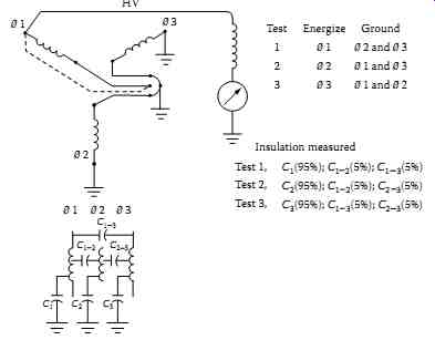
FIG. 22 PF measurement of ground-wall insulation.
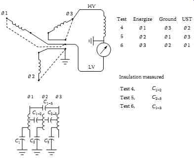
FIG. 23 PF measurement of interphase (end-turn) insulation.
6.8.1 PF Tip-Up Test
Another variation of the PF tests on machine winding insulation may be performed as a PF tip-up test. The PF tip-up is defined as the increase in the PF as the voltage is increased from an initial test value to the maximum test value. The PF tip-up test can be performed on any dry-type insulation, that is insulation not immersed in insulating oil, such as dry-type transformers, motors, etc. The PF tip-up test indicates the nature of insulation contamination and degradation which is voltage dependent, such as carbonization and ionization. It shows the increase in dielectric loss as a function of voltage, thereby indicating the cause of the increased losses. The PF tip-up test is illustrated by an example given in TABLE In this example, PF tests are conducted starting at an initial voltage value of 2 kV, with i ve steps of 2 kV each to a maximum value of 10 kV. The PF test voltages and corresponding measured PF values for each test are shown in TABLE The PF tip-up between test 1 and test 5 is 0.8% (test 5 minus test 1). Similarly PF tip-up can be calculated for each succeeding test to determine the PF tip-up. Increasing value of PF tip-up indicates increased dielectric losses due to increased voltage, thus indicating degradation that is sensitive to increasing voltage.
If the tip-up value is small or the increase in tip-up value is small, it indicates that the insulation degradation is not voltage dependent, such as the case when the winding insulation is wet or contaminated with moisture.
TABLE 10 PF Tip-Up Test of a Machine Winding
6.9 Cables and Accessories
PF testing of cables requires additional precautions since cables are run in duct banks and conduits or are directly buried in ground, and are not visible other than the ends of the cable. Therefore both ends of the cable under test should be clearly identified and isolated. Additional concern involves the ground return path of the current to the test set. Effective PF test can only be performed for the shielded and sheathed cables. It is recommended that PF test for unshielded or unsheathed cables should only be performed if a definite ground return path can be provided back to the test set. Also, because of the long lengths of cables (large capacitance), the charging cur rent of these cables may be very large and beyond the capacity of the PF test set. As a result, the PF tests can be performed on relatively short lengths of cables. PF tests are not very effective in detecting localized faults as the length of the cable under test increases. However, PF tests are useful in indicating general deterioration and contamination of the cable. The hot collar tests discussed earlier in this section under bushings are most effective tests for cable accessories, such as pot heads. The PF tests for cables are divided into shielded and sheathed cables and unshielded and unsheathed cables which are discussed in Sections 6.9.1 and 6.9.2.
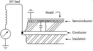
FIG. 24 PF test connection of single-conductor shielded cable.
6.9.1 Shielded or Sheathed Cable
The single conductor cable should be de-energized, isolated, and grounded to discharge the cable completely before conducting a PF test on it. The HV lead of the PF test set is connected to the cable conductor and the cable shield or sheath is effectively grounded as shown in FIG. 24. The test is con ducted in the GST mode and the voltage of sufficient magnitude (voltage should not exceed the cable's normal operating voltage) is applied depending upon the voltage rating of the cable. Multiconductor cables which are individually shielded can be tested similar to the single conductor shielded cables with the other cables not under test effectively grounded.
6.9.2 Unshielded and Unsheathed Cables
The single conductor unshielded or unsheathed cable may be tested similar to the single conductor shielded cable. However, the test results (measurement of the PF) may include PF measurements of other materials surrounding the cable or any materials that form the ground return path of the leakage current. In other words, the losses in materials that are not part of the insulation are included in the PF measurement, thus giving unpredictably higher PF results. Also, it is unsafe to conduct the PF test in this manner since the return leakage current path is not exactly known and therefore may pose a danger to the test operator. Therefore this procedure is not recommended. Instead, if PF tests are to be conducted on such cables then the procedure recommended is to use another phase conductor of the same circuit (or a spare cable if available) as a leakage current return path by connecting the far ends of two cables. The test is performed in the UST mode to conduct PF test measurement between the two cables. Similarly, multiconductor unshielded or unsheathed cables may be tested in this manner. Any other cables not included in the test should be effectively grounded. This procedure is repeated to include all conductors in at least one measurement.
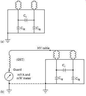
FIG. 25 (a) Capacitance associated with a two bushing capacitor; (b)
PF test connections for measuring ground insulation of a two bushing capacitor.
6.10 PF Correction Capacitors and Surge Capacitors
The PF capacitors are used to improve system (load) PF or phase angle.
The surge capacitors are used with surge arrestors to protect motors by changing the slope of the wave front of voltage surges. Both of these types of capacitors have relatively high capacitances. The PF correction capacitors are either a single or two bushing design, while the surge capacitors are always a single bushing design. The two bushing capacitor has capacitances known as main capacitance C1 which is between the two bushing; ground capacitance C1g between bushing one and ground; ground capacitance C2g between bushing two and ground which are shown in FIG. 25a. The main capacitance C1 because of its largeness is generally beyond the range of the 2.5 kV PF test set, but the ground capacitance of two bushing can be tested with the 2.5 kV PF test set as shown in FIG. 25b.
Although this method does not measure the main insulation, it is effective in detecting problems associated with the bushing and internal ground-wall insulation. The capacitor, the housing, and both bushing should be grounded to completely discharge the unit before any PF tests are made on these units. This caution applies to all units that have been just removed from service and others that have not been energized. The PF test is made in the GST mode for checking the ground capacitance and UST mode for checking the main capacitance C1.
6.10.1 Bus Insulators
One-piece porcelain bus insulators can be tested individually by the dielectric loss method. The procedure consists of grounding the bus and insulator base, and applying the test voltage to the center of the porcelain as shown in FIG. 26. The test measures the dielectric losses in the top and lower halves of the insulator in parallel to ground. The test potential should be applied to the porcelain busing by a snug-fitting hot collar. Average values of millivolt-amperes and milliwatts should be calculated for a number of similar insulators. The insulators that have dielectric losses appreciably higher than the average should be removed for further tests and examined for cracks and internal contamination.
6.10.2 Miscellaneous Equipment
Other miscellaneous electrical equipment that can be tested for PF are coupling capacitors, hot sticks, bus insulators, rubber gloves and blankets, and bucket trucks. These types of equipment are beyond the scope of work of this text. It is recommended that the reader refer to the manufacturers of the PF test equipment for guidance on PF testing of such equipment.
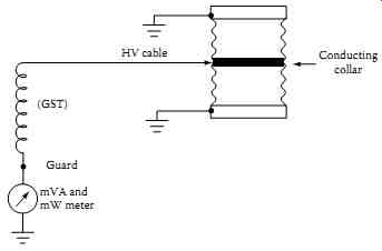
FIG. 26 Test connections for one-piece post-type bus insulator.