AMAZON multi-meters discounts AMAZON oscilloscope discounts
7. Testing and Commissioning of Static and Digital Relays
The differences between static (second and third generation) and digital relays (fourth generation) were listed in Sections 3.2.2 through 3.2.4, respectively. As it was mentioned, the earlier versions of static relays are not equipped with automatic self-test features therefore they may require more attention than the digital relays having self-test features. The inspection and maintenance of static and digital relays can be addressed under each relay type. The following is a guide for inspecting and testing static relays.
Static relays
Static relays should be tested in accordance with manufacturer's recommendations given in relay instruction books. As there are no moving parts in static relays, there is no physical wear due to usage and no need for lubricants.
Prime causes of failure in electronic components are heat, vibration, and moisture. Overheating can be caused by voltage transients, current surges, excessive power, or high ambient temperature. Vibration can loosen or break leads and connections and can crack component casings or insulation resulting in equipment failure. Moisture can result in corrosion of metallic elements which can result in circuit discontinuities, poor contact, or shorts. Preventive maintenance of static relays should be directed toward removing causes of failure listed above by doing the following:
Keep equipment clean by periodic vacuuming or blowing out of dirt, dust, and other surface contaminants Keep the equipment dry and protected against moisture and corrosion Inspect to see that all connections, leads, and contacts are tight and free as possible from effects of vibration Check to see that there is adequate ventilation to conduct heat away efficiently Preventive measures should not be applied unnecessarily as this may con tribute to failures. For example, printed circuit cards should not be pulled from their racks to be inspected if there is no real need. Operating test switches unnecessarily may introduce damaging voltage transients.
Digital relays
Digital relays are built using a microprocessor, an AC signal data acquisition system, memory components containing the relay algorithms, contact inputs to control the relay, and contact outputs to control other equipment. Digital relay operating characteristics are defined by the algorithms and settings contained in the relay memory.
As mentioned earlier, digital relays are often equipped with automatic self test functions. These self-tests verify correct operation of critical relay components. If a self-test detects an abnormal condition, it can close an output contact, send a message, or provide some other indication of the failure.
When the alarm occurs, a technician can be dispatched to repair or replace the device quickly.
The analog input section is typically monitored by automatic self testing. This may be somewhat limited because a steady-state condition cannot be fully defined. With a protective relay, there are often many steady-state conditions possible under each mode of operation. Since the analog input portion of the digital relay is only partially self-tested, routine maintenance assists in verification of the analog measuring components.
Many digital relays offer metering features which give the user a convenient means of verifying the accuracy of the relay analog input section. The user can verify metering quantities and be assured the relay is using valid data for its relay element computations. This practice is sound if the digital relay uses the same measuring circuitry for both metering and relaying.
On the other hand, if the relay uses separate circuitry for its metering functions, the metering data checks only the components common to both the metering and relaying circuitry.
The contact input/output circuitry is another part of the digital relay which allows only partial automatic testing. For this reason, it may be appropriate to implement a routine trip check. Many digital relays provide a trip feature which allows the user to locally or remotely trip the relay. The trip check verifies the trip circuit wiring and the integrity of the trip coil. This trip command feature provides a convenient means of tripping the circuit breaker without the need to inject a simulated fault to the relay. If the relay is routinely operating for faults, the actual relay operations may be adequate verification of the relay input/output functions.
The digital processing section, typically a microprocessor, is the interface between the analog input section and the contact input/output section.
Since the analog and contact input/output sections cannot function without the processing section, normal relay use and maintenance checks act as routine verification of the microprocessor. Additionally, manufacturers are able to offer very thorough self-tests to continually monitor the status of the computer.
Engineers should work closely with relay vendors to determine what relay functions are not checked by relay self-tests and how those functions should be checked in the field. In the case of the processing section, there are typically no special tests required.
Many of the maintenance features are executable by remote command and often could replace routine maintenance altogether. Also, consider the analysis of digital relay fault data comparable to routine relay maintenance. Those relays which do not encounter faults may require more thorough routine maintenance checks.
Digital relay routine testing practices should verify relay functions that cannot be fully verified by the relay self-testing. FIG. 16 shows how all relay failures can be detected using a regime consisting of:
• Self-test alarm monitoring
• Loss of signal (loss of voltage [LOV] and loss of current [LOI]) monitoring Review of relay event reports
• Periodic checks of relay inputs and outputs
• Periodic calibration check by comparison
• Relay self-testing and event data analysis detect the majority of relay failures. Monitoring LOV and LOI functions, executing meter tests and input/ output checks verify the balance of relay functions. Taken together, this regime replaces complex routine tests. These simple tests can be performed quickly, minimizing the need for complex test equipment.
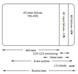
FIG. 16 Digital relay self-testing and monitoring functions entirely replace
traditional routine tests. (From Kumm, J., et al., Assessing the effectiveness
of self-tests and other monitoring means in protective relays, SEL Technical
Papers, p. 4, 1995. Courtesy of SEL, Inc., Pullman, WA.)
7.1 Test Methods
Test methods can be separated into three primary categories:
• Steady-state testing
• Dynamic testing
• End-to-end testing
Steady-state testing is the most common method for testing a digital relay.
As the name implies, steady-state values are applied to characterize the relay performance or verify settings. For example, when testing a distance element a fixed voltage level is applied to the relay and the current is slowly increased until the element operates. The relay accuracy, characteristics, timing, and operation of internal logic can easily be verified. Note that steady-state testing does not truly represent a faulted condition on the power system. Sudden changes in current and voltage magnitudes, phase angles, and DC offset are not used.
Steady-state testing requires that the tester or the test developer have an understanding of the internal relay logic, especially in a multifunction digital relays. Again, referring to the distance element example, many supervisory elements are included in the distance element final output.
If the relay experiences a loss of the source voltage, the distance element is blocked from operation. During steady-state testing it is likely that a loss of voltage element would set and block the distance element output thus making it appear that it is not operating correctly. Fortunately, most digital relays allow the user to disable these supervisory functions for test purposes.
Dynamic testing is designed to represent the actual power system conditions the relay may see in the application. In this case, normal load conditions are applied to the relay before a fault is applied. Normal load conditions could mean nominal voltages and currents, or just nominal current, depending upon the type of relay. Power system parameters are used to determine the fault quantities. Line and source impedances are entered into a program to calculate the fault currents and voltages at certain locations on the protected line. The test is performed by applying the prefault current and voltages for a period of time, then suddenly changing to the fault values. Some test sets have the capability of supply DC offset current to more accurately represent the power system conditions.
End-to-end testing is similar to dynamic testing. The same types of signals that are used to perform dynamic testing are also used for end-to-end testing.
The primary difference is that the relays are tested at their respective installation sites with all of the equipment connected to the relay. For example, circuit breakers, communications equipments, and other auxiliary devices.
The test sets are time synchronized using a satellite clock signal providing a high accuracy time source. The test sequences are initiated at all locations simultaneously and the response of the relay is evaluated as if the test were an actual fault condition.
7.2 Commissioning Methods
The purpose of commission tests is to verify that the relay has been set correctly and that all functionality is operating as expected. Unlike electromechanical relays, the operating characteristic of the digital relay does not change, therefore, it is unnecessary to do a complete series of test verifying all of the operating characteristics. Commissioning tests should be focused in the following areas:
• Settings
• Protection function checks
• Communication checks
• Auxiliary power checks
• Other checks
Testing should be complete enough to verify that the relay settings have been entered correctly. Comparison of the expected settings against the entered setting is relatively easy to do with the support of a settings manager or program. Tests should verify that the elements operate at the specified settings. Check pickup of overcurrent elements, time delays, distance element reaches, and custom logic. It is not necessary to check unused functions. In addition, testing should be limited to that required to verify settings, it is not necessary to test the complete operating characteristic of the relay. For example, it is not necessary to test the entire circular characteristic of a mho distance element. The pickup at the maximum reach and the maximum torque angle setting only need to be checked.
Another example would be a time overcurrent element. Check pickup set ting and two or three points on the timing curve to verify that the correct curve shape and time dial have been selected.
Digital relays include many functions and features, this is one of the advantages of using digital relays, however, it can also make them somewhat complex and difficult to test. Testing should be focused on the functions that are used in the specific application. In many cases, customized logic is implemented to meet specific application needs. As recommended previously, it is unnecessary to test all of the internal protection logic. Instead, test the logic that requires user input, for example, output logic, trip logic, input logic, etc.
Digital relays also provide various means of communications. Communications can be used for data and status information for a SCADA system, engineering access for events and setting changes, and communications between devices for high-speed protection schemes. Communication is typically via a serial port, either RS232 or RS485, however, many relays also offer Ethernet communications. Communications logic and data should be verified through the entire system. For example, SCADA communications through a DNP master should be verified to the control center. The appropriate information and data should be sent and confirmed. Digital communications between devices should also be verified. Some schemes require delays to account for communications channel and these should be checked to ensure secure operation.
Verify the battery system and all connected devices. Also verify the cur rent and voltage circuits, this includes checking monitoring functions like loss-of-potential detection.
Develop a test plan when testing digital relays. A well thought out test plan ensures that all of the aspects of the scheme will be correctly tested and documented. Use AC and DC schematics, communications diagrams, and the relay settings to determine what and how the relay should be tested.
Developing a checklist for verification and testing is very helpful in assuring that everything is thoroughly tested and documented. For example, a test list for a line protection system may include items such as:
• Primary protection function checkout
• Auxiliary protection function checkout
• Control functions
• Relay logic; fixed and user programmed
• Physical mounting
• Electrical connections
• Setting verification
• Communications; protection and data monitoring
• Security
• In-service checks
Customize the checklist to suite the specific application. A well thought out test program will have long-term benefits in reuse and troubleshooting in the future.
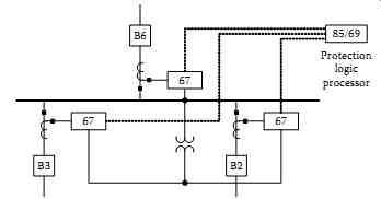
FIG. 17 Fast bus trip one-line diagram.
7.3 Commissioning Examples
The following two examples show commissioning practices for a bus protection scheme and a transformer differential scheme.
Bus protection scheme
The first example illustrates commissioning of microprocessor relays for a fast bus transfer protection system using a protection processor. Figure. 9.17 shows a one-line diagram of a distribution bus protection scheme using a fast bus trip scheme.
Most of the logic for the protection of this scheme is developed in the settings of a protection logic processor (85/69 device). Thus, to successfully commission this scheme, we need to verify the performance of the following:
• Directional overcurrent elements (67)
• Performance of the communications path
• CT and VT connections and polarities of the inputs to the 67 devices
• Fast bus trip and block logic settings in relays and protection logic processor Breaker trip/DC control circuit
• The directional overcurrent elements can be tested and validated by applying test values from system faults (e.g., internal bus fault, external line faults).
CT and VT polarities, phasing, and ratios are usually checked through manual field measurements at commissioning. One improvement is to use synchrophasor data from the relays, if available. Phasor measurements take a precise snapshot of the currents and voltages at the same instant in time.
Commissioning the communications path and logic settings is more complex and requires that the logic be broken out into logic diagrams.
Ideally, we would like to test the scheme all the way through. The best environment for this is a laboratory simulation with all three relays and the protection logic processor connected with complete AC voltage and current and the entire communications scheme connected.
For example, individually test directional overcurrent elements (67) for breakers 2, 3, and 6. Then apply fault simulations for each scenario to verify the internal and external fault logic (expected results are shown in parentheses):
1. Breakers 3, 6 internal, breaker 2 external (no trip).
2. Breakers 2, 6 internal, breaker 3 external (no trip).
3. Breakers 2, 3 internal, breaker 6 external (no trip).
4. Breakers 2, 3, 6 internal (trip within 25 ms).
5. Verify transient reversal block logic by applying test 1, then test 4 in short intervals, e.g., apply test 1 for two cycles, then test 4 for four cycles, etc. (no trip).
6. Verify disable fast bus trip logic by applying loss of potential (LOP) and relay out of service conditions, then apply test 4 (no trip).
By performing a thorough laboratory simulation of the complete logic, we can then install and commission this system. In the field, we check the CTs and VTs, verify the integrity of the communications path, and perform breaker trip tests to validate the DC control circuit.
Transformer differential scheme
The example shows a method for commissioning microprocessor relays for a transformer differential scheme. Commissioning transformer differential protection schemes involves several levels of testing:
Hardware tests verify transformer turns ratio, CT turns ratios, and CT polarity.
Functional tests validate the performance of the relay elements with the installed settings and test the DC control circuits. Trip tests verify that the relay operates the correct lockout relays and breakers.
In-service or commissioning tests verify the primary and secondary AC current circuits. We must take into account the transformer ratio and connection; the CT ratio, wiring, and connections; and the relay settings.
The last item is, by far, the most challenging aspect of assuring certainty in commissioning, modern transformer differential relays have settings that compensate for the difference in the secondary currents, adjusting for the transformer connection (e.g., delta-wye) and removing zero-sequence current.
In order to perform commissioning tests, we must apply balanced three phase currents to the primary system. Some users energize the transformer to the system and begin to apply load. Ideally, we prefer to perform this test without connecting to the power system. For example, use a portable generator or a station service transformer to supply a reduced voltage three-phase power supply to one of the windings of the transformer and apply a short-circuit to the remaining winding. An example test setup is shown in FIG. 18.
Through this procedure, we can check the following:
The phase rotation and angle of the currents
Secondary current magnitudes
The relationship of the high-side currents to the low-side currents
The operating or differential current (should be nearly zero)
For the transformer shown in FIG. 18, given a 240 V AC source, we can calculate expected relay currents (magnitude and angle). Using relay metering data, we then observe the measured currents, as shown in Table 4. If the measured (actual) currents do not match the calculated (expected) currents and/or we observe differential current, we must perform troubleshooting to systematically check CT wiring, connections, and relay settings to correct the discrepancy.
Sometimes it helps to plot the currents, as shown in FIG. 19. Winding 2 B-phase and C-phase currents in this system appear to be reversed.
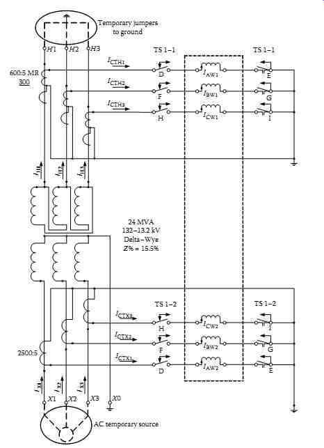
FIG. 18 Three-line diagram of primary injection test. (From Zimmerman,
K., Commissioning of protective relay systems, SEL Technical Papers, p. 4,
2007. Courtesy of SEL, Inc., Pullman, WA.)
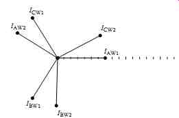
FIG. 19 Plots of measured currents during commissioning test. (From Zimmerman,
K., Commissioning of protective relay systems, SEL Technical Papers, p. 5,
2007. Courtesy of SEL, Inc., Pullman, WA.)
FIG. 20 Example of an event report. (figure coming soon)
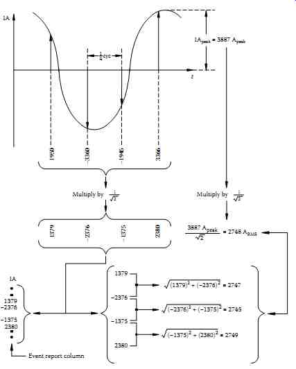
FIG. 21 Derivation of current and rms current values from sampled waveform.
(From Costello, D., Understanding and analyzing event report information
(WPRC 2000), SEL Technical Papers, p. 5, 2000. Courtesy of SEL, Inc., Pullman,
WA.)
8. Event Reporting
Event reporting is a standard feature in most microprocessor-based protective relays. The data and information saved in these reports are valuable for testing, measuring performance, analyzing problems, and identifying deficiencies before they cause future misoperations.
Event reports indicate whether the protective relay operated as expected.
In addition, analysis identifies whether all associated components of the protect ion system were installed and operated correctly. Power system model s, settings, wiring, auxiliary relays, circuit breakers, current and VTs, communications equipment, the DC battery system, and connected loads can all be measured and monitored by analyzing event report data.
Every time the power system faults and relays capture data, you have readymade test reports. By analyzing actual relay and system performance, you can save money by extending or eliminating traditional routine tests.
When faults or other system events occur, protective relays record sampled analog currents and voltages, the status of optoisolated inputs and output contacts, the state of all relay elements and programmable logic, and the relay settings. The result is an event report, a stored record of what the relay saw and how it responded. With readily available information from product instruction manuals, the user is provided with all the necessary tools to determine if the response of the relay and the protection system was correct for the given system conditions.
Event reports are formatted ASCII text files that are read vertically. Time increments as we read down the page, and data are displayed in columns.
Each horizontal row represents a particular point in time. FIG. 20 displays an example event report from a distribution relay.
The analog data in FIG. 20 are reported every quarter-cycle or 90 electrical degrees. This makes it simple to take one sample, the oldest or previous, as the y-component and the next sample, the newest or present, as the x-component of a phasor current or voltage. Modern relays, including the one that generated the event report in FIG. 20, are capable of sampling much faster, as much as 16 to 64 samples per cycle, for better resolution and oscillography. However, the relays continue to offer the analyst a choice of display rates: 16 samples per cycle for generating detailed oscillography or four samples per cycle for quick visual analysis.
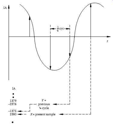
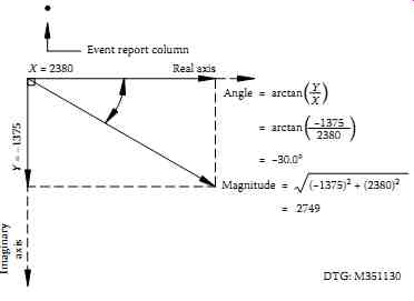
FIG. 22 Derivation of phasor rms current values from sampled waveform.
(From Costello, D., Under standing and analyzing event report information
(WPRC 2000), SEL Technical Papers, p. 6, 2000. Courtesy of SEL, Inc., Pullman,
WA.)
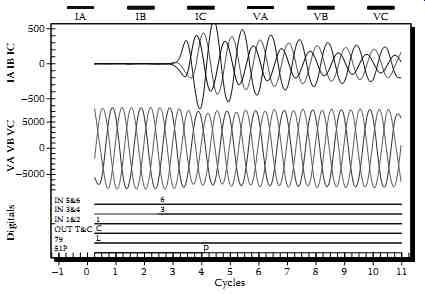
FIG. 23 Manual close of a failed distribution recloser.
FIG. 21 shows how the event report AC current column data relate to the actual sampled waveform and rms values. Note that any two rows of data, taken one quarter-cycle apart, can be used to calculate rms values. If an event report is displayed in a 16-sample per cycle format, every fourth row of data could be used to calculate rms values. FIG. 22 shows how to convert the event report current column data to phasor rms values. Process voltages similarly.
Event report analysis can reveal problems with power system models, settings, breakers and auxiliary contacts, instrument transformers, and more. In the past, these problems would go undetected until they were either caught during routine maintenance or more serious consequences occurred. It is a good practice to examine every event report to see if the operation was normal or exceptional.
The FIG. 23 shows a graphical plot of a typical event report. Analog and digital information can be analyzed using readily available software.
The graphical plots are very useful for observing the actual waveforms and timing of the digital elements.
Event reports are useful in monitoring the following protection system components: protective relays, substation batteries, DC wiring, auxiliary tripping relays, circuit breakers, trip and close coils, breaker auxiliary con tacts, CTs, AC wiring, VTs, communications equipment, settings and logic, power system models, and more.