AMAZON multi-meters discounts AMAZON oscilloscope discounts
1 Low-Voltage Switchgear
Low-voltage switchgear is a commonly used name for metal-enclosed or metal-clad low-voltage power circuit breaker switchgear rated for 600 V alternating current (AC) and below. The metal-enclosed switchgear assembly is completely enclosed on all sides and top with sheet metal (except for ventilating openings and inspection windows) and contains stationary primary power circuit switching or interrupting devices, or both, with buses and connections. The metal-clad low-voltage switchgear contains circuit breakers of removable (rack-out) types which are housed in individual grounded metal compartments. The construction features of metal-enclosed and metal-clad switchgear were described previously in Section 7. The service conditions for the design and performance of low-voltage switchgear are based upon ambient temperature from -30°C to +40°C, altitude not to exceed 6000 ft, and switchgear installed in non-explosive atmosphere.
There are two basic types of low-voltage switchgear structures, they are indoor and outdoor types. Indoor switchgear consists of a front section containing circuit breakers, meters, relays and controls, bus section, and cable entrance section. The outdoor section is similar to the indoor switchgear except a structure that is provided around it for weatherproofing. Bus bars are available either in copper or aluminum. When aluminum bus is specified, bolted joints should be made with Belleville washers to minimize cold flow characteristics and maintain tight connections. Generally, bare bus bars are used. However, insulation can be specified on special orders. The normal clearance between phase to phase and phase to ground is 2 in. to minimize creepage for 600V rated equipment. The standard high-voltage withstand is 2200 V AC for phase to phase and phase to ground for a period of 1 min.
Totally enclosed low-voltage switchgear, in its present form, began to gain acceptance through the 1950s. The manufacturers of the time marketed three pole circuit breakers and their enclosures as equipment that was safer for the user's personnel, more reliable, and as having advantages over fuses; namely, prevention of single phasing on three-phase AC systems. Today, low-voltage switchgear takes on many specialized forms and functions that combine metering, monitoring, control, protection, and distribution. Major manufacturers, i.e., original equipment manufacturers (OEMs), and specialty panel shops now provide a wide variety of low-voltage switchgear designs, some of them very custom, to suit the user's needs. These may or may not be Underwriters Laboratory (UL)-labeled. It is common to find installations where several different kinds of circuit breakers, automatic controls, and monitoring devices, and even automatic transfer switches, will be combined in the same line-up.
This trend in integration has started to confuse the issue as to what low-voltage switchgear really is. It should be borne in mind that switchgear is still some principal combination of metal enclosures with multipole circuit breakers. There are many metal-enclosed, dead front, assemblies offered that are switch and fuse combinations. Although they look like and commonly are referred to as switchgear, they are really modern versions of equipment known as switchboards, and are called that by most manufacturers. Like their forerunners, these switchboards do not address the problems with single phasing on branch feeders due to a blown fuse; however, the incoming device may have phase loss or blown fuse detection included in it. Regarding current-carrying capacity, both fuses and switches have roughly kept pace with the developments in circuit breaker technology.
Low-voltage AC switchgear designs are still widely applied to low-voltage direct current (DC) distribution centers up to 250 V. Previously, manufacturers provided two-pole, draw-out circuit breakers for DC switchgear. Today, the same three-pole design, and three-phase bus arrangement, is provided for both DC and AC applications; with the extra pole either unused or placed in series with one of the others according to the particular manufacturer's application preferences. As of this writing, direct-acting overcurrent trip devices are not offered for the new low voltage power circuit breakers. The direct acting and electromechanical trip devices have been replaced by microprocessor based (electronic) trip devices for overcurrent protection. However, in the molded and insulated case low voltage circuit breakers both electronic and thermal-magnetic overcurrent trip devices are offered. The electro mechanical and direct-acting trip devices are still available in the secondary market as replacement for the older low voltage power circuit breakers.
Low-voltage generator paralleling switchgear continues to become more commonplace as utilities and consumers strike agreements for cogeneration or load curtailment contracts. Although similar in form to unit substation type switchgear, it is vastly more sophisticated in the areas of protection and control. It is common today to see low-voltage switchgear with protective relaying that used to be found only on medium-voltage switchgear in a utility's generating station.
2 Low-Voltage Circuit Breakers
Low-voltage circuit breakers that may be found in switchgear, distribution centers, and service entrance equipment are of three types: (1) molded-case circuit breakers (MCCBs); (2) insulated-case circuit breakers; and (3) fixed or draw-out power circuit breakers.
2.1 MCCBs
MCCBs are available in a wide range of ratings and are generally used for low-current, low-energy power circuits. The breakers have self-contained overcurrent trip elements. Conventional thermal-magnetic circuit breakers employ a thermal bimetallic element that has inverse time-current characteristics for overload protection and a magnetic trip element for short-circuit protection.
Conventional MCCBs with thermal-magnetic trip elements depend on the total thermal mass for their proper tripping characteristics. This means that the proper sized wire and lug assemblies, which correspond to the rating of the trip element, must be used on the load terminals of such breakers. Many manufacturers are now switching over from bimetallic elements to power sensor (electronic) type trip elements. Magnetic-trip-only breakers have no thermal element. Such breakers are principally used only for short-circuit protection. Molded-case breakers with magnetic only trips find their application in motor circuit protection. This arrangement is desirable for smaller motors where their inrush current can ruin a delicate thermal element but where protection for winding failure is still needed.
The breaker provides the instantaneous (INST) protection and fault interruption, and other overload devices in the starter handle the long-time overload protection. Nonautomatic circuit breakers have no overload or short-circuit protection.
They are primarily used for manual switching and isolation.
2.2 Insulated-Case Circuit Breakers
Insulated-case circuit breakers are molded-case breakers using glass- reinforced insulating material for increased dielectric strength. In addition, they have push-to-open button, rotary-operated low-torque handles with independent spring-charged mechanism providing quick-make, quick break protection. A choice of various automatic trip units is available in the insulated-case breakers. Continuous current ratings range up to 4000 A with interrupting capacities through 200,000 A. The principal differences between insulated-case breakers and heavy-duty power circuit breakers are cost, physical size, and ease of maintenance. Insulated-case breakers are not designed with easy troubleshooting or repairs as the principal feature; whereas, draw-out power circuit breakers are. To partially compensate for this drawback, many manufacturers now offer a variety of accessories for insulated-case breakers that can duplicate the features of their more expensive counterparts. Nevertheless, insulated-case breakers are generally suited to light industry or commercial buildings where frequent or numerous operations are not expected.
2.3 Power Circuit Breakers
Heavy-duty power circuit breakers employ spring-operated, stored-energy mechanisms for quick-make, quick-break manual or electric operation.
Generally, these breakers have draw-out features whereby individual breakers can be put into test and fully de-energized position for testing and maintenance purposes. The electrically operated breakers are actuated by a motor and cam system or a spring release solenoid for closing. Tripping action is actuated by one or more trip solenoids (shunt trip coil) or flux operated devices; generally one for the protective devices on the breaker itself, and another for externally mounted controls or protective devices. The continuous frame ratings for these breakers range from 400 to 4000 A. Some manufacturers have introduced breakers with 5000 and 6000 A frames; how ever, the long-term benefits and overall reliability of these designs have yet to be proven in the field. Short-circuit interrupting capabilities for these breakers are usually 50,000-85,000 A root-mean-square (rms) for frame sizes up to 4000 A. Larger designs have approached 100 kA. These breakers can be extended for applications up to 200 kA interrupting when equipped with assemblies or trucks designed to hold Class L, current-limiting power fuses.
2.4 Fused Power Circuit Breakers
The trend toward larger unit substation transformers and larger connected kVA loads on such substations has given way to power circuit breakers in tested combination with current-limiting fuses. This is routinely done in order to increase the short-circuit interrupting rating of the switchgear. This combination can be used for all frame sizes. The fuses cause the same problems with single phasing as fuses in the switchboards; however, there are numerous features that compensate for this problem. First, most fuse assemblies are attached directly to the breakers themselves so fuses cannot be removed or installed unless the breaker is out of service. Most manufacturers solve the single-phasing problem by either an electrical or a mechanical means of blown fuse detection, which in turn causes the breaker to trip immediately after the fuse has cleared. On the largest frame sizes, where the fuses must be mounted apart from the breaker cubicle, the fuse assembly is on a truck or roll-out which is mechanically interlocked with the breaker it serves. It should be noted that the overcurrent protection for overloads is still handled by the breaker's overcurrent trip devices, and that the fuse is not expected to clear except for the most severe short circuits.
3 Overcurrent Protective Devices
The low-voltage overcurrent protective devices are direct-acting (electro mechanical) trip (series trip) and static (electronic) trip. These overcurrent protective devices are used in the power circuit breakers as discussed above.
3.1 Direct-Acting Trip
The direct acting overcurrent trip device is also known as series trip, electro mechanical and dashpot trip device This device utilizes the force created by the short-circuit current flowing through it to trip its circuit breaker by direct mechanical action. These devices are operated by (1) an electromagnetic force created by the short-circuit current flowing through the trip device coil (the trip coil is usually connected in series with the electrical circuit or in some instances to the secondary of current transformers) or (2) a bimetallic strip actuated by the head generated by the fault current. The bimetallic strip is usually connected in series with the circuit.
A combination of thermal (bimetallic strip or equivalent) and INST magnetic trip is commonly used on molded-case breakers to provide time delay operation for moderate overcurrents (overloads) and INST operation for high- magnitude of short-circuit current. The thermal trip is usually nonadjustable in the field or there are some devices that have limited range of adjustment, such as 0.8 to 1.25, whereas the instantaneous (INST) trip is available as adjustable or nonadjustable. The adjustable-trip range varies from low to high with several intermediate steps. The number of steps available may vary for different designs and sizes.
Direct-acting trips on insulated-case and heavy-duty power circuit breakers are of the electromagnetic type. Three trip devices are available: (1) long time delay (LTD), (2) short time delay (STD), and (3) INST. Any combination of the three types is available to provide protection for overcurrents. A trip device is installed in each phase of the electrical circuit. The LTD, STD, and INST trip devices are available in minimum, intermediate, and maximum time bands to facilitate the coordination of various trip devices in series. All these units have adjustable settings.
The time delay bands are accomplished by the action of the solenoid's pull against springs, pneumatic, or hydraulic devices. Since these elements are purely mechanical, different characteristics cannot be supplied in a single trip device. Although some calibration points and some effects on the time can be changed by adjustments, completely different delay bands can be selected only by physically changing out the trip devices with others of the desired type.
Direct-acting trips are still used on some applications, and are still required on power circuit breakers used on DC unit substations.
3.2 Static- and Electronic-Trip Units
Static-trip devices are completely static; that is, there are no moving parts.
These devices use semiconductor-integrated circuits, capacitors, transformers, and other electric components. Static-trip devices operate to open the circuit breaker when the current-time relationship exceeds a preselected value.
The energy required to trip the breaker is obtained from the circuit being protected. No external power, such as DC batteries, is required. The complete static-trip system is comprised of (1) primary circuit current transformers, (2) the static logic box, and (3) the tripping actuator (a magnetically held latch device).
The current transformer sensors are of toroidal type mounted one per phase on the primary studs of the circuit breaker. These transformers pro vide a signal to the static-trip device proportional to the primary current.
The static logic box receives the signal from the primary current transformer.
It monitors the signal, senses overloads or faults, and executes the required action in accordance with preselected settings. The tripping actuator receives the output signal from the static logic box and in turn causes the circuit breaker contacts to open.
Manufacturers have made great strides in the development and application of solid-state trip devices over the past 10 years or so. The motivation for this effort has been to bring protective devices to market that offer improved features over the original direct-acting designs yet preserve the totally self contained concept exhibited by their forerunners. When the static trips were first introduced, manufacturers struggled to provide reliable and repeatable devices that would prove to be lower maintenance items than the ones they replaced. Their difficulties were not easy to overcome. The main problem has always been related to a consistent and accurate method to both derive operational power from the signals resulting from current flowing through the breaker, and to accurately measure the current at the same time. The developments came one by one. For some time, most manufacturers still had to rely on a magnetic device to get an INST function. The designs of that time did not allow an electronic device to build up sufficient power to trip the actuator fast enough to be called INST.
Some designs have used (and may still use) two sets of current sensors, or one set of sensors with dual secondary windings, in order to derive a signal to monitor and another to act as the power supply. Additional sensors may be required for a function that direct-acting trips could not offer- ground fault. Both three-phase, three-wire; and three-phase, four-wire ground fault detection systems are offered. The signals from either the three or four sensors are processed to determine if all INST currents add up to zero (Kirchoff's current law applied to three-phase AC systems). Therefore, it should be apparent that if grounding conductors are used, they should not be included along with any neutral connections. When current returns to its source via a ground conductor, the monitored currents no longer add up to zero and the trip device activates. The connections and current sensors used for a three-phase, four-wire, plus ground conductor on a feeder breaker are shown in FIG. 1.
Advances and enhancements are continually being made on static and electronic-trip devices. For example, the older type static- and electronic-trip elements measured peak and/or average currents and then scaled these currents to rms values based on the properties of pure sine wave. Therefore, the older static- and electronic-trip elements along with the electromechanical analog type trip elements are susceptible to tripping problems due to harmonic cur rents generated by nonlinear loads. The nonlinear loads are variable speed drives, switch-mode power supplies, electronic ballasts, and the like. The cur rent electronic units are truly microprocessor based and are programmed to sample the current waveform at required intervals to calculate the effective rms value of the load currents. Microprocessor trip elements with rms sensing avoid false tripping problems due to harmonic current peaks and sense the true heating current in the circuit. In addition, microprocessor trip elements provide the capability for digital readouts of voltage, currents, kilo watts, kilowatt demands, kilowatt hours, kilovars, power factor, frequency, and so on. These readouts can be local or can be interfaced to a remote location via digital communication network. Some microprocessor protection packages can provide additional protection features that were originally available only by means of installing additional protective relays.
Also, the current microprocessor trip elements have less energy requirements for static-trip logic. In general, most designs now use fewer and smaller current sensors than would have been supplied for the breaker whose schematic is shown in FIG. 1. A good example of a modern static-trip device is the Micro-VersaTrip, RMS-9 Programmer (MVT) offered by General Electric distribution and control which is shown in FIG. 2. Not only does this device offer all of the features mentioned above but also it has the ability to measure the true rms current. This makes the breaker immune to false trip ping due to current waveforms with high distortion or harmonic content.
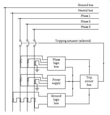
FIG. 1 Functional diagram of static-trip device.
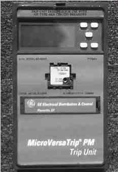
FIG. 2 Micro-VersaTrip Plus, static-trip device.
The MVT system consists of the following parts.
Three current sensors are mounted on the breaker and provide the self-powered input to the protection programmer. Where four-wire ground fault is specified, a fourth current sensor is mounted near the neutral bar in the cable compartment. Sensors are constructed of molded epoxy for added protection against damage and moisture. Optional current sensors with four taps are available to increase the flexibility and range of the system. In the current designs rating plug is provided for a given sensor and breaker to establish the continuous current carrying capability (rating) of the breaker.
A flux-shift device is automatically powered and controlled by the protection programmer and causes the breaker to trip on command. This low-energy positive action tripping device is located near the trip bar on the breaker. This device automatically resets when the moving contacts on the breaker have fully opened.
The protection programmer has a programmable microelectronic processor with laser-trimmed custom-integrated chips that form the basis of the flexible, precise MVT protection system. MVT protection programmers may be furnished with:
- Up to nine adjustable time-current functions
- Three local and remote mechanical fault indicators
- Local and remote long-time pickup light emitting diode (LED) indicator
- Zone selective interlocking
- Integral ground-fault trip
All adjustable programmer functions are automatic and self-contained and require no external relaying, power supply, or accessories.
3.3 Monitoring and Protection Packages
A natural outgrowth of the move to static-trip devices has been to provide devices that can display the quantities they are monitoring. This trend has come in response to user's concerns regarding the convenience in monitoring loads and in troubleshooting a given distribution system. Low-voltage switchgear generally has space constraints within its breaker cubicles; consequently, mounting space (if any) for additional current transformers is limited. Manufacturers are beginning to offer monitoring packages that take advantage of the signals already made available by the protection devices. The information can be displayed on the trip device or sent to a cubicle door mounted display. Automated data processing centers and cogeneration sites have set up elaborate monitoring systems by taking advantage of the communications functions that are now offered. Almost every feeder at a user's site can be monitored and all of its electrical performance data sent back to a central system. The trend in interfacing this basic electrical monitoring with communications to field programming units (FPUs); remote terminal units (RTUs), programmable controllers (PLCs) used as sequence controllers, data collectors, or concentrators; and sequence control and data acquisition (SCADA) systems is expected to continue. Many of the elements used in these systems are now installed directly in the switchgear.