AMAZON multi-meters discounts AMAZON oscilloscope discounts
6. DC ( Battery) Control Power Equipment
The following is offered as a general guide for the selection and application of DC battery equipment.
6.1 Sizing
The duty cycle imposed on the battery will depend on the DC system design and the load requirements. The duty cycle showing the battery loads in amperes and the lengths of time for which they must be supported will determine the sizing of the battery. Loads may be classified as continuous or noncontinuous.
Continuous loads are classified as steady-state loads and noncontinuous loads lasting 1 min or less are known as momentary loads or short-time loads.
Continuous loads are energized throughout the duty cycle and are normally supplied by the battery charger.
Examples of typical continuous loads are:
• Lighting
• Indicating lights
• Continuously energized coils and operating motors
• Inverters and annunciator loads
Examples of typical noncontinuous loads are:
• Circuit breaker operations
• Motor operated valves
• Inrush currents of motors or other devices
• Field flashing of generators or synchronous motors
To size a control power source, each type of load must be known. For batteries, the steady-state and short-time loads must be converted to a common rate base. Also, the long-time loads must have specified time periods, since the battery is not a continuous source when the charger is off. After all the loads have been totaled, the next higher size of control power source should be selected. The reader is urged to consult IEEE standard 485-1997 (P485/D5, May 2008), "IEEE recommended practice for sizing large lead storage batteries for generating stations and substations" when selecting a battery for control power or other usage.
The capacity of the battery is usually expressed in ampere-hours, that is, the product of discharge current and time in hours. The basic rate is normally expressed for 8h; however, many other rates are used to express battery capacity. In switchgear application, the short-time rates, such as 1 min rate per cell, is frequently used to express the terminal voltage drop early in the discharge period. The manufacturer's data are usually given for cells at 25°C (77°F), and when the battery is at a lower temperature than the stated temperature, the battery rating must be reduced. The voltage drop due to discharge current specified in terms of 1 min rate per cell for a nickel-cadmium battery is 1.14 V, and 1.75 V for the lead-acid battery, at 25°C.
To convert the 1 min rate loads to the equivalent ampere-hours rate, the battery or switchgear manufacturer should be consulted. For sizing the capacity of a battery for switchgear, the worst case should be assumed. The worst case occurs when the battery has carried steady-state load for 8 h and then is subjected to maximum load involving 1 min rate. However, it is not uncommon for some installations to require batteries to be sized to carry the anticipated control and tripping loads for up to 24 h. For indoor locations, the battery temperature is assumed to be 25°C, and for outdoor application, -10°C.
6.2 Types of Batteries
For switchgear applications, two types of batteries are used: lead-acid batteries (flooded cells and valve regulated) and nickel-cadmium batteries. Lead-acid batteries are made in several types:
Pasted plate with lead-antimony grids:
This is a basic lead-acid battery, similar to the common automobile battery. However, for switchgear control work thicker plates and lower gravity of acid pro vide longer life. It is also suitable for long-time float charging. The expected life of this battery is from 6 to 14 years depending upon the plate thickness. It is also the lowest-cost battery.
Lead-calcium: This is basically pasted-plate construction, with antimony replaced by calcium for additional grid strength. It has an expected life of about 25 years. Because of pure lead electrochemical characteristics, it requires slightly different charging voltages.
Tubular positive: This is also known as an iron-clad battery. These batteries are suitable for large stations and long-time load applications.
Plante: This is a long-life battery, with expected life of 20-25 years.
In this battery, the positive plate is formed form pure lead. Its short-term rates are somewhat higher and ampere-hours slightly less as compared to pasted-plate types. This is the most expensive lead-acid battery.
Valve-regulated lead-acid (VRLA): This is also known as maintenance free battery. The cells of this battery are sealed with the exception of a valve that opens to atmospheric pressure by a preselected amount.
This battery provides means for recombination of internally generated oxygen and the suppression of hydrogen to limit water usage. The cells of this battery are sealed from the environment unless internal pressure operates the release valve.
Round cell battery: This is a pure lead-acid battery which has round cells instead of rectangular cells as found in the conventional battery.
The geometrical shape assures uniform growth, while the pure lead grid provides for slower plate growth as compared to lead-calcium or lead-antimony.
The nickel-cadmium battery is constructed with pocket-plate cells for switchgear applications. The battery plates have three different construction thicknesses. Medium or thin plate construction is used for switchgear applications. The maintenance of nickel-cadmium battery is less than the maintenance for lead-acid. Its low-temperature discharge currents are higher, and it can be charged more rapidly than lead-acid batteries. The cost of the nickel-cadmium battery is higher than the lead-acid battery.
6.3 Battery Chargers
Two types of battery chargers are available for switchgear control power.
One is known as the trickle-charge, which is the unregulated type, and the other is the regulated type. The regulated charger provides longer life, especially for lead-acid batteries. The regulated charger is recommended for switchgear applications. The selection of charger equipment should satisfy the following functions simultaneously:
- Steady-state loads on the battery
- Self-discharge losses of the battery
- Equalizing charges
Steady-state loads are those that require power continuously. Self-discharge losses are due to trickle current, which starts at about 0.25% of the 8 h rate for lead-acid batteries. Self-discharge losses increase with the age of the battery.
The equalizing charge is an extended normal charge and is given periodically to ensure that the cells are restored to the maximum specific gravity. All lead- acid batteries require a monthly equalizing charge except the lead- calcium type. Nickel-cadmium batteries do not require the equalizing charge; however, it is recommended for occasional boosting. In the sizing of charger equipment, the steady-state loads, equalizing-charge current, and self- discharge current should be added to arrive at the capacity of the charger. Select a charger with ratings that exceed or equal the sum of currents required.
7. AC Control Power Equipment
The following is a general guide for the selection and application of AC control power equipment.
7.1 Sizing
For sizing the capacity of an AC control potential transformer, all the loads should be totaled. These loads may be steady state, breaker closing, and tripping.
If the tripping is provided by a capacitor trip device, the tripping demand may not be included. The closing demand of breakers that require simultaneous closing should be totaled and included in sizing the control transformer.
The total load should then be compared to the available sizes of control power transformers, and the next larger size should be selected.
7.2 Application
It is recommended that the control power be supplied from a separate transformer strictly used for control purposes. This will minimize inadvertent loss of control power. The transformer should be connected to the bus or the line side of the circuit to minimize control power interruption. For multiple services, each service should have its own control power source. Circuits that are not exclusively associated with either source should be supplied control power automatically from either of the control power transformers in case of loss of one control source.
8. Maintenance and Care of Batteries for Switchgear Applications
The monitoring and maintenance of batteries for switchgear applications is very important from the point of view of service reliability. The consequences of electrical failures are catastrophic in cases where no control power is avail able for tripping the circuit breakers. Proper maintenance is the key to depend able battery operation. The reader is referred to IEEE standard 450-2002,
"IEEE recommended practice for maintenance, testing, and replacement of vented lead-acid batteries for stationary applications" for maintenance and testing procedures that can be used to care for these batteries. The following is a summary of battery maintenance procedures derived from the above referenced standard that are offered as a guide to ensure long life and depend able service. Refer to Section 8.9 for detailed inspection checklist on batteries installed for UPS applications since there are many similarities common to both of these battery systems.
8.1 Inspections
Periodic inspection can provide information on the battery conditions and its state of health. All inspections should be made under normal float conditions.
Inspection should be made at least once a month (and more frequently, such as weekly depending on service), and should include the following checks:
- Float voltage at battery terminals
- Charger output current and voltage
- General appearance and cleanliness of the battery
- Electrolyte levels, cracks in jars, and leakage of electrolyte
- Evidence of corrosion at terminals, connectors, racks, or cabinets
- Voltage, specific gravity, and electrolyte temperature of pilot cells
- Ambient temperature and ventilation
- Unintentional battery grounds
The monthly inspection should be augmented once every quarter with the following checks:
- Voltage of each cell and total battery terminal voltage
- Specific gravity of 10% of the cells of the battery
- Temperature of electrolyte of 10% of the cells of the battery
The yearly inspection should include the following checks:
- Detail visual inspection of each cell to determine its condition
- Specific gravity, voltage, electrolyte level, and temperature of each cell of the battery
- Contact resistance of cell-to-cell and terminal connections
- Impedance measurements of the battery cells
- Structural integrity of the battery rack and cabinet
8.2 Equalizing Charge
The station batteries are sized in terms of their discharge capacity, which is usually stated in ampere-hours. The ampere-hours are based on supply current during an 8 or 4 h period with electrolyte temperature at 25°C. To maintain a constant voltage at the battery terminals, the charger is connected in parallel with the battery and the load circuits. The purpose of the float charge voltage is to prevent the internal discharge of the battery. The practical float voltages are listed in terms of volts per cell (VPC). Following are the VPC values for the various types of batteries:
- Nickel-cadmium: 1.4-1.42 VPC
- Lead-calcium: 2.17-2.25 VPC
- Lead-antimony: 2.15-2.17 VPC
- Plante: 2.17-2.19 VPC
When the battery is equipped with a constant voltage charger, it is automatically charged after an emergency discharge. In the case of lead-acid batteries, a periodic equalizing charge is required when the specific gravity, corrected for temperature, of an individual cell falls below the manufacturer's lower limit (or below its full-charge value by 0.001), or the individual cell float voltage(s) deviate from the average value by ±0.05 V (typical value of lead-antimony cells is ±0.03 V). As an alternative, when an individual cell corrected for temperature is below 2.13 V (typical for nominal 1.215 specific gravity cells), equalizing charge to the entire battery should be initiated immediately.
However, it is often more convenient to apply the equalizing charge to the individual cell if there is one or few cells out of limit. The frequency for equalizing charging varies, but is usually from a minimum of 3 months to 1 year. Also, an equalizing charge should be given to a battery after the addition of water to the battery. Different types of batteries require different lengths of time for the equalizing charge. The length of time is a function of cell temperatures. A normal electrolyte value for specific gravity based on a temperature of 77°F is taken to be 1.15 for a fully charged lead-acid battery. Battery performance is affected by electrolyte temperature. Generally, for every 3°F below 77°F, the battery performance can be evaluated by subtracting 0.001 from the specific gravity. Similarly, for every 3°F above 77°F, add 0.001 to the specific gravity. Specific gravity readings may not accurately indicate state of battery charge following discharge or following addition of water. The most accurate indicator of return to full charge is stabilized charging or float current.
8.3 Battery Tests
The following tests are performed to:
- Determine whether the battery meets its specifications or the manufacturer's rating or both
- Periodically determine whether the performance of the battery, as found, is within acceptable limits
- Determine whether the battery, as found, meets the design requirements of the system to which it is connected, i.e., whether it has the capacity and capability to power the loads connected to it
8.3.1 Acceptance Test
This is the test to determine whether the battery meets a specific discharge rate and duration in accordance with manufacturer's ratings. This test is normally made at the factory or upon initial installation.
8.3.2 Performance Test
In IEEE standard 450-2002, it is recommended that the battery capacity test should be made within the first 2 years and followed by a test interval not to be greater than 25% of the expected service life. Assuming a service life of 25 years for a vented cell battery, then this test should be conducted every 5 years or less until the battery shows signs of degradation. Similarly, in IEEE standard 1188-2005 it is recommended that the performance test interval for VRLA batteries should not be greater than 25% of the expected service life or 2 years, whichever is less. Further, annual performance test should be con ducted on any battery that shows signs of degradation or has reached 85% of its service life. Degradation is indicated if the battery capacity falls more than 10% from its capacity on the previous performance test, or 90% of the manufacturer's rating.
8.3.3 Battery Service Test (Load Test)
A service test of the battery is normally made to satisfy that the battery can meet its load profile, that is, its duty cycle. This test is also known as load cycle test. When a service test is conducted on a regular basis, it will indicate whether the battery indeed can perform its intended function. Therefore, this test may be conducted on an annual basis. Trending battery voltage during the critical periods of the load test can provide information when the battery will no longer meet its design requirements. In IEEE standard 450-2002 and IEEE standard 1188-2005, this test is referred to as service test and it is recommend that this test be conducted between the cycle of the performance tests. When a service test is also being used on a regular basis it will reflect maintenance practices and the health of the battery to meet its design requirements. When a battery shows signs of degradation, service testing should be continued to be performed on its normal frequency.
Several manufacturers have built programmable battery load testers and market them for conducting the service (load) test. The Torkel Programmable Load Unit Battery load tester, manufactured by Megger Instruments is shown in FIG. 32.
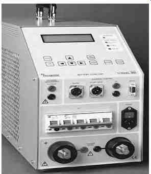
FIG. 32 Torkel Programmable Load Unit Battery tester. (Courtesy of Megger
Instruments, Valley Forge, PA.)
8.3.4 Connection Resistance Test
The connection resistance of the intercell connections and terminal connections can be made with the use of digital low-resistance ohmmeter to assess the integrity of the current (conduction) path. Normal connection resistance varies with the cell size and connection type, and ranges from less than 10 µO for a large battery to as much as 100 µO for a smaller battery. Periodic measurements should be made, such as annually, and compared to previous years value to determine the need for corrective action for maintenance.
A 20% change from the previous years baseline values, or values that exceed the manufacturer's limits should initiate the need for corrective action. Refer to IEEE standard 450-2002 for more details on this method.
8.3.5 Battery Impedance Test
This test is based on the principle that the electrical properties of the battery, such as impedance changes proportionally with a battery's age and discharge history. The relative internal impedance of a cell increases due mainly to losses of active material as its capacity decreases. As the cells age naturally, a life curve can be plotted for a cell and compared to a generic curve of similar cell to indicate degradation or life expectancy. The intercell impedance can be measured by using a low-frequency current source. The object of the test is to pass current through the battery string and measure the resultant voltage drop across each cell, and then compute the cell impedance. This test can be performed during float conditions without disconnecting the battery. The impedance tester, manufactured by Megger Instruments is shown in FIG. 33.
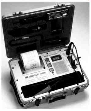
FIG. 33 Battery impedance tester (BITE). (Courtesy of Megger, Inc., Dallas,
TX.)
When interpreting test results, it should be noted that change in cell impedance is also affected by other factors, such as temperature, state of the charge, load conditions, or combination of all these. These conditions should be monitored and recorded before making measurements.
Impedance readings for the individual cells can be used in the short-term to compare with the average impedance reading for the entire battery. Individual cell values that vary by more than ±20% of the battery average typically indicate a problem with that cell. Impedance readings of the entire battery can be used in the long-term to determine the need for replacement. Battery cell impedance values should be recorded and compared to previous readings to determine the position of the cell on the curve of impedance versus cell life. A sample curve for a generic lead-acid cell is shown in FIG. 34. Curves may differ for other manufacturer batteries and battery chemistries. The reader may want to consult Megger Instruments who maintains a database of cell impedance values for many battery manufacturers at various temperatures, applications, and cell age.
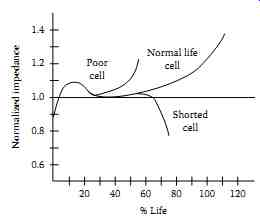
FIG. 34 Impedance versus cell life (lead-acid battery). (Courtesy of Megger,
Inc., Dallas, TX.)
8.4 Addition of Water
Due to charging, the battery will normally lose water through evaporation and chemical action. Distilled water must be added to the battery, preferably before the equalizing charge is applied.
8.5 Acid Spillage
When acid is spilled on the battery exterior, it should be wiped clean with a cloth dampened in baking soda solution. Furthermore, the battery exterior should be wiped dry after wiping with a water-dampened cloth following the initial cleaning.
8.6 Loose Connections
Battery terminal connections and intercell connections should be checked periodically as discussed in Section 3.4.
8.7 Corrosion
All corrosion on battery terminals should be removed by applying baking soda solution and the terminals cleaned by using a brass brush. Antioxidant coating should be applied before reconnecting.
8.9 Other Maintenance Hints
- Do not ground the electric storage battery, because a second accidental ground on the ungrounded polarity of any circuit fed by the battery would cause the control circuit fuse to blow
- New batteries after initial charge should be kept on float charge for a week
- Take weekly readings of the voltage of selected cells and total battery voltage
- Take monthly readings of electrolyte level, cell voltage, specific gravity, and temperature
- Every 3 months to 1 year, take a complete set of cell readings