AMAZON multi-meters discounts AMAZON oscilloscope discounts
3 Electrical Switchgear Maintenance and Care
Switchgear components, such as circuit breakers, disconnect switches, fuses, and insulators, require regular inspection and maintenance. Switchgear can be of indoor or outdoor type and can be from different manufacturers.
However, the maintenance of all types of switchgear can be carried out by following the basic maintenance operations. Also refer to Section 8.7.1, Section 8 on general guidelines for inspection of switchgear that may be used when inspecting medium voltage switchgear. This section provides the fundamental maintenance instructions for an overall maintenance program for switchgear. In cases where detailed instructions are required, the reader is advised to consult the recommendations of the manufacturer of the particular equipment under consideration for maintenance.
3.1 MV Switchgear
3.1.1 Power Circuit Breakers
MV circuit breakers consist of air-magnetic circuit breakers either of horizontal drawout type or vertical lift type, oil circuit breakers, and vacuum circuit breakers. The following procedures should be carried out before new power circuit breakers are placed in service.
a. Receiving, handling, and storage
Inspect the circuit breaker for damage that may have occurred in transit.
Check the nameplate data and the packing list provided with the equipment delivered.
Inspect the arc chutes of the air-magnetic breaker for cracks, damage, or foreign material.
Inspect the shield on each of the fixed arcing contacts of the air-magnetic breaker for cracks.
Lift and let down circuit breakers slowly. Do not use the bushing as handles when handling the breaker. Always roll and maneuver the breaker by grasping the top edge of the breaker cover. Avoid any sudden jerks when moving the breaker.
If the breaker must be stored before it is put into service, keep it in a clean, dry, and noncorrosive place. Coat all bare metal surfaces with grease to prevent rusting or oxidation. If the breaker is to be installed outdoors, make sure power is available for space heaters and that they are working.
In cases where a breaker is stored for a long period of time, it should be inspected regularly for rusting.
b. Installation
Make an overall examination of the entire breaker to ensure that there are no damaged parts.
Use a dry, clean cloth to remove dirt and moisture that might have collected on the circuit breaker.
Cycle the breaker by opening and closing the breaker manually and electrically. Check for proper operation.
To ensure that no damage has occurred during shipment, perform a high-potential (hi-pot) test on each breaker pole (or vacuum interrupter) while the breaker is in the open position. Test results should be evaluated on a go, no-go basis by slowly raising the test voltage to the values shown in Table 6. Hold the final test value for 1 min, if using an AC test method. If you are using a DC test method, you can operate the test using a Megger Vidar that takes only 5-10s. If you do not get good results when testing a vacuum interrupter using the DC method, then first retest the vacuum bottle using reverse polarity. At that point, if the bottle fails again, then you will have to check it with an AC hi-pot instrument.
Visually inspect the breaker before installation to make sure that all test jumpers or leads, specialized breaker tools or maintenance accessories have been removed before installing the breaker in its cubicle.
Install the breaker into its cubicle in accordance with manufacturer's instructions. Check for proper operation by manually cycling the breaker with control power off. This should be done while the breaker is in the test or disconnected position.
TABLE 6 Hi-Pot Values for Acceptance Testing of Breakers
3.1.2 Maintenance
Power circuit breakers, like other electrical equipment, require preventive maintenance to avoid equipment problems. The schedule for preventive maintenance can vary for each facility depending upon operating and environmental conditions. Frequent inspection and maintenance should be performed if the following factors are present:
- Corrosive atmosphere
- Excessive dust or dirt
- High ambient temperature and high humidity
- Older equipment
- Excessive repetitive duty
- Frequent fault interruption
Generally, the frequency of inspection should be based upon service and operating conditions. As a guide, inspect equipment about 6 months after it is installed and the follow up with scheduled maintenance every 1-3 years.
In the performance of maintenance routines, all safety precautions should be followed.
Preventive maintenance should include the following areas:
1. Circuit breaker
a. Contacts
b. Arc chutes
c. Mechanical parts
d. Auxiliary equipment
2. Cell enclosure
a. Cell joints (i.e., bus joints)
b. Cell contacts
c. Insulation
The following routine maintenance instructions are offered as a general guide for the maintenance of power circuit breakers. If special detailed instructions are required, consult the manufacturer.
3.2 Air-Magnetic Circuit Breakers
Before inspecting or performing any maintenance on either the breaker or its mechanism, be sure the breaker is in the open position, is disconnected from all electrical sources, and is removed from the cubicle ( FIG. 13a, b, and c). Both the closing and opening, springs should be discharged or blocked mechanically before any maintenance is done. The old air magnetic breakers, in many cases have been retrofitted (replaced) with vacuum breakers in the same switchgear. The vacuum breaker retrofit is a direct one-for-one replacement without involving any other equipment conversions. For maintenance of vacuum breakers in retrofit applications, refer to Section 7.3.4 for guide lines and instructions on vacuum breakers.
1. Record the number of operations and perform a general visual inspection of the breaker. Report any unusual signs of problems.
2. Put circuit breaker in test position and, using a test coupler, operate breaker electrically. Check the operation of all electrical relays, sole noid switches, motors, control switches, and indicating devices.
3. Remove circuit breaker from enclosure and perform visual inspection as follows:
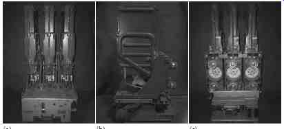
FIG. 13 An ITE air magnetic breaker components. (a) Front view showing arc-chutes,
(b) side view showing bushing and operating mechanism, and (c) back view showing
disconnecting stubs and cluster fingers.
a. Remove box barriers.
b. Wipe clean of smoke deposit and dust from all insulating parts, including the bushings and the inside of the box barrier. Use a clean, dry, lint-free cloth; a vacuum cleaner would be helpful.
c. Inspect the condition of bushing primary disconnect stubs and finger cluster.
d. Inspect the condition of bushing insulation; it should be clean, dry, smooth, hard, and unmarred.
e. Check breaker and operating mechanism carefully for loose nuts, bolts, or retaining rings, and ensure that mechanical link age is secure.
f. Inspect insulation and outside of arc chutes for holes or breaks; small cracks are normal.
g. Inspect magnetic blowout coils (if used) for damage.
h. Inspect all current-carrying parts for evidence of overheating.
Functional inspection
Sand throat area of arc chutes with garnet paper or other nonconductive, abrasive paper until thoroughly clean.
Ensure that arc chutes are clear of contamination and have no significant damage on grids or ceramics. If ceramics or fins are broken, replace arc chutes.
Ensure that all brazed, soldered, or bolted electrical connections are tight.
Inspect contacts of control relays for wear and clean as necessary.
Check actuator relays, charging motor, and secondary disconnects for damage, evidence of overheating, or insulation breakdown.
Check that all wiring connections are tight and for any possible damage to the insulation.
Replace any wire that has worn insulation.
On stored-energy breakers, operate the breaker slowly. By using the spring blocking device, check for binding or friction and correct if necessary. Make sure contacts can be opened or closed fully.
Inspect the arcing contacts for uneven wear or damage. Replace badly worn contacts. Measure the arcing contact wire, using an ohm meter. Make adjustment if necessary. Refer to the appropriate instruction book.
Inspect primary contacts for burns or pitting. Wipe contacts with clean cloth. Replace badly burned or pitted contacts. Rough or galled contacts should be smoothed with a crocus cloth or file lightly.
Resilver where necessary.
Inspect primary disconnect studs for arcing or burning. Clean and lightly grease arcing contacts.
Check primary contact gap and wipe. Make adjustment as per appropriate instruction book. Grease contacts with an approved grease and operate breaker several times.
Check operation and clearance of trip armature travel and release latch as per appropriate instruction book. Replace worn parts.
Inspect all bearings, cams, rollers, latches, and buffer blocks for wear.
• Teflon-coated sleeve bearings do not require lubrication. All other sleeve bearings, rollers, and needle bearings should be lubricated with SAE 20 or 30 machine oil. All ground surfaces coated with dark molybdenum disulfide do not require lubrication. Lubricate all other ground surfaces such as latches, rollers, or props with an approved grease.
• Install box barriers.
• Measure insulation resistance of each bushing terminal to ground and phase to phase. Record readings along with temperature and humidity.
• Perform hi-pot test for breaker bushing insulation (optional).
• Check closed breaker contact resistance (optional).
• Perform power factor test (optional).
• Perform corona test (optional).
• Using test box, operate breaker both electrically and manually. Check all interlocks.
• Insert and operate breaker in cabinet. Watch for proper operation of the positive interlock trip-free mechanism. (Breaker should trip if not fully in or in test position.)
• Remove breaker from cubicle and check primary disconnect wipe; refer to appropriate instruction book.
• Perform visual inspection and check for proper operation as discussed under Section 3.1.1.b before inserting breaker into cubicle ready for energization.
3.3 Oil Circuit Breaker
The oil circuit breaker should be maintained on a periodic basis similar to the air-magnetic circuit breakers. To maintain the circuit breaker, mount it on the inspection rack and untank it to expose the internal parts. Check for the following and make adjustments and repairs in accordance with the instruction book.
Wipe clean all parts, including any carbon markings. Insulating parts should be inspected for damage such as warp age and cracks; replace damaged parts.
Inspect the contacts for alignment and wear. Replace pitted and burned contacts and file rough contacts. Adjust contacts to ensure that contacts bear with firm and even pressure.
Take an oil sample and make a dielectric test as explained in Section 4 under testing of insulating liquids. If visible carbon particles are evident in the oil, filter oil regardless of the dielectric strength.
Wipe inside of tank, barriers, and tank linings to remove carbon.
Inspect and clean operating mechanism similar to that described in Section 3.2.
Check the breaker operation by slowly closing with the closing device similar to the air-magnetic breaker. Also check its electrical operation.
Replace tank with proper oil level and make sure that all gaskets, tank nuts, and flange nuts are tightened properly to prevent leakage.
3.4 Vacuum Circuit Breaker
The vacuum circuit breaker ( FIG. 14a and b) maintenance schedule should be based upon operating experience and environmental conditions.
If such a schedule has not been determined, it is recommended that the breaker be inspected at least once a year or every 2000 operations, whichever occurs earlier. However, a breaker should be inspected every time after a severe fault interruption. The following checks should be performed for the vacuum circuit breaker:
Check for contact erosion. To determine contact erosion, remove breaker from enclosure. Close the breaker and measure the spring plate overtravel. Consult the manufacturer's instruction book for allowable overtravel. If the specified overtravel is exceeded, the vacuum interrupter must be replaced.
To check the condition of the vacuum, perform a hi-pot rest. Consult the manufacturer's instruction book for test value or use 60% of the final factory test value.
Using a clean, dry cloth remove all dirt and moisture from the outside of vacuum interrupters and all insulating parts.
Check the entire operating mechanism similar to the air-magnetic circuit breaker.
Lubricate ground surfaces such as cams, gear teeth, rollers, and pawls when performing maintenance. See the manufacturer's guide on lubrication methods and time periods.
Operate the breaker manually and electrically several times to make sure that the breaker is operating properly.
Electrical tests of the vacuum bottle integrity can be performed using either an AC or DC method. Also, vacuum bottle integrity can be checked using a DC Megger Vidar Instrument. The test using a Vidar only takes 5-10 s.
A Megger Vidar instrument is shown in FIG. 15.
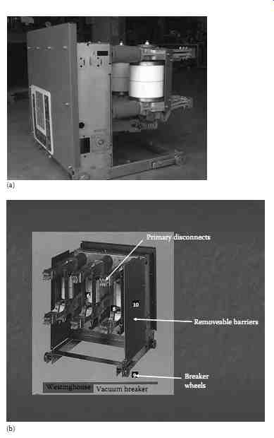
FIG. 14 Medium voltage power/vacuum circuit breaker. (a) Side view showing
vacuum bottles and (b) back view showing primary disconnect fingers.
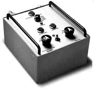
FIG. 15 A DC Megger Vidar instrument. (Courtesy of Megger/Programma, Valley
Forge, PA.)
3.5 Switchgear Enclosure and Bus
An inspection of the switchgear bus and enclosure should be made every year. However, inspection frequency can be increased or decreased depending on operating and environmental conditions. It is good practice to follow the manufacturer's recommendations regarding maintenance procedures. The following are suggestions to supplement the manufacturer's recommendations:
Check the enclosure housing to ensure that all hardware is in place and in good condition. The purpose of enclosure is to protect the equipment from outside contaminants and prevent exposure of personnel to live parts. A maintenance program should assure that these features are maintained. Lubricate hinges, locks, latches, and so on.
For outdoor assemblies, check for roof or wall leaks, as well as for damage from previous leaks.
After the power has been turned off and the bus has been grounded, remove dust and dirt by wiping with a dry, clean cloth or by vacuuming.
Check for all unnecessary floor openings and any water pools at the base of enclosures. Seal such openings with duct seal. Check for signs of moisture accumulation, such as droplet depression on dust laden surfaces and dust patterns. Prevent moisture accumulation by providing heat and ventilation. Therefore, make sure that space heaters and fans are functioning properly.
Check that ventilators are clear of obstruction and air filters are clean and in good condition.
The surface of all insulating members should be inspected before any cleaning or dusting, as well as after cleaning for signs of electrical distress, tracking, corona, and thermal heating. Damage caused by electrical distress will usually be evident on the insulating surface as corona markings or tracking parts. The areas most susceptible to electrical distress are:
a. Splices and junction points
b. Boundaries between adjoining insulators
c. Edges of insulation surrounding mounting hardware grounded to the metal structure
d. Bridging paths across insulating surface
e. Boundaries between an insulating member and the grounded metal surface
f. Hidden surfaces such as adjacent edges between upper and lower members of split bus supports
g. Sharp edges in switchgear that are not insulated Check for loose bolted connections in bus bars, splices, and the like, for signs of heating. Tighten in accordance with manufacturer's recommendations.
Examine grounding connections and ground bus for tightness and cleanliness.
Check alignment and contacts of primary disconnecting devices for abnormal wear or damage. Check for sulfide deposits and use a solvent such as alcohol for removal of these deposits.
Remove any paint damage or finishes.
After cleaning and adjusting, run an insulation resistance test to measure resistance to ground. Compare the values of test readings with previous readings for any sign of weakening of the insulation system. Readings should be normalized to a common temperature and humidity base before comparison is made.
Compare equipment nameplate information with latest one-line diagram and report discrepancies.
Check tightness of accessible bolted bus joints by calibrated wrench method. Refer to manufacturer recommendations for proper torque values.
Test key interlock systems physically to ensure the following:
a. Closure attempt should be made on locked-open devices
b. Opening attempt should be made on locked-closed devices
c. Key exchange should be made with devices operated in off normal positions
Check for cracks in extruded red sleeving bus insulation made from Lexan or Noryl. Repair cracked insulation according to manufacturer's recommendations.
4. Electrical Switchgear Testing
The design of the insulation system for metal-enclosed switchgear is based upon life expectancy of about 30 years. However, environmental conditions such as dirt, moisture, and corrosive atmosphere can shorten the design life.
Moisture combined with dirt is the greatest deteriorating factor for insulation systems because of leakage and tracking, which will result in eventual failure.
Therefore, it is important to maintain the switchgear insulation and to chart the condition of the primary insulation system by routine testing.
The electrical switchgear may be tested with AC or DC voltage to check the condition of the insulation of switchgear and circuit breakers. Before con ducting any other tests, an insulation resistance test (Megger) should always be conducted first to determine if it is safe to conduct other HV tests. Also when testing circuit breakers, it is important to check the condition of the circuit breaker contacts and circuit breaker operating mechanism to assure that the circuit breaker is opening and closing as designed. These tests are listed and discussed as follows:
- Insulation resistance test
- DC or AC hi-pot test
- Power factor or dielectric loss test
- Circuit breaker contact resistance test
- Circuit breaker time-travel analysis test
4.1 Insulation Resistance Measurement Test
The insulation resistance measurement test may be conducted on all types of electrical switchgear using the insulation resistance megohmmeter commonly known as the MEGGER.* The Megger S1-5010 is shown in FIG. 16 that may be used to perform this test.
The insulation resistance test consists of applying voltage (600-10,000 V DC) to the apparatus to determine the megohm value of resistance. This test does not indicate the quality of primary insulation. Several factors should be remembered when performing this test. The first is that this test can indicate low values of insulation resistance because of many parallel paths. The other is that an insulation system having low dielectric strength may indicate high resistance values. In view of this, the test results should only be interpreted for comparative purposes. This does not indicate the quality of the primary insulation system from the point of view of dielectric “withstandability”. The connection diagram for making this test on a power circuit breaker is shown in FIG. 17. When performing insulation testing, it is recommended that auxiliary equipment, such as potential transformers and lightning arresters, be removed from the stationary switchgear.
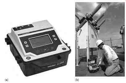
FIG. 16 Megger S1-5010 for making insulation resistance tests. (a) Megger
S1-5010; (b) Megger S1-5010 being used in the field. (Courtesy of Megger, Inc.,
Valley Forge, PA.)
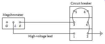
FIG. 17 Typical connection for insulation resistance test of circuit breaker
in open position.
TABLE 7 DC Hi-Pot Maintenance Test Values
Insulation resistance tests are made with the circuit breaker in open and closed position, whereas the insulation test for the switchgear bus is made with one phase to ground at a time, with the other two phases grounded.
The procedure for this test is as follows:
Circuit breaker open: • Connect HV lead to pole 1. Ground all other poles.
Repeat for poles 2 through 6, in turn, with other poles grounded.
Circuit breaker closed: • Connect HV lead to pole 1 or 2, as convenient, with either pole of phase 2 and 3 grounded. Repeat for phases 2 and 3 with other phases grounded.
Stationary gear (buses): • Connect HV lead to phase 1 with phases 2 and 3 grounded. Repeat the same for phases 2 and 3 with other phases grounded. Also, perform IR tests between phase 1 and 2 with phase 3 grounded, phase 2 and phase 3 with phase 1 grounded, and phase 3 and 1 with phase 2 grounded.
4.2 DC Hi-Pot Test
The DC hi-pot test is normally not made for AC electrical switchgear and therefore may be considered only when AC hi-pot cannot be performed. The hi-pot testing of switchgear involves testing of the circuit breakers and switch gear buses separately. This is a major test and determines the condition of the insulation of the switchgear assembly. The DC hi-pot test is not preferred for testing AC switchgear because the application of DC voltage does not pro duce similar stress in the insulation system as is produced under operating conditions. Moreover, the DC hi-pot test produces corona and tracking owing to concentration of stress at sharp edges or end points of buses. The corona and tracking are more pronounced in older equipment, and it is therefore recommended that DC hi-pot testing be avoided on such equipment.
The test procedures for DC hi-pot testing are similar to those of AC hi-pot testing and are described in detail in Section 2. If DC hi-pot testing is to be performed, the DC voltage test values shown in Table 7 are recommended for various voltage-class equipment.
The hi-pot test should be conducted under conditions similar to those of commercial testing. The switchgear should be wiped, cleaned, and restored to good condition before the hi-pot test is conducted. Temperature and humidity readings should be recorded and the test reading corrected when conducting DC tests.
4.3 AC Hi-Pot Test
This test should be conducted separately for circuit breakers and switchgear buses (stationary gear). It should be made only after the DC insulation resistance measurement test has been passed satisfactorily and all cleanup has been finished. The AC test will stress the switchgear insulation similarly to the stresses found during operating conditions. The maintenance test voltages should be 75% of final factory test voltage. These values are shown in Table 8.
Hi-pot tests are made with the circuit breaker in both open and closed positions.
The hi-pot test should be the last test conducted after all repairs have been made, cleanup is finished, and the insulation resistance test has been successfully passed. Procedures for the hi-pot test of the circuit breaker are as follows:
The test connection for the hi-pot test is as shown in FIG. 18.
• Circuit breaker in open position:
• Connect HV lead to pole 6. Ground all other poles. Repeat for poles 1 through 5, in turn, with all other poles grounded. Apply the desired high voltage in each case in accordance with Table 8.
Circuit breaker in closed position:
• Connect HV lead to pole 1 or 2 or phase 1 as convenient with either pole of phases 2 and 3 grounded.
Repeat for test for phases 2 and 3 with other phases grounded.
Stationary gear (buses):
• Connect HV lead to phase 1 as convenient with phases 2 and 3 grounded. Apply the recommended voltage.
Repeat the test for phases 2 and 3 with other phases grounded.
TABLE 8 Hi-Pot Test Values
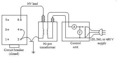
FIG. 18 Typical connection for hi-pot test for circuit breaker in closed
position.
4.4 Power Factor Testing
The power factor testing of an insulation system is useful in finding signs of insulation deterioration. The absolute values of power factor measured have little significance. However, comparative analysis of values from year to year may very well show insulation deterioration. Therefore, when a power factor test is made, it should be made under the same conditions of temperature and humidity. If differences exist in the temperature and humidity from year to year, this should be taken into consideration when evaluating the test data. Generally, higher temperature and humidity result in higher power factor values. As a general rule, only the air circuit breaker bushing should be power factored, and the arc chutes, operating rods, and so on, should be disconnected when conducting this test. A significant change, especially an increase in watts loss or percent of power factor indicates deterioration, which should be monitored. As a general rule, a power factor below 1% indicates good insulation. Any value above 1% warrants investigation. Power factor tests are discussed in more detail in Section 3.
4.5 Circuit Breaker Contact Resistance Measurement Test
Stationary and moving contacts are built from alloys that are formulated to endure the stresses of electrical arcing. However, if contacts are not maintained on a regular basis, their electrical resistance due to repeated arcing builds up, resulting in a significant decrease in the contact's ability to carry current. Excessive corrosion of contacts is detrimental to the breaker performance. One way to check contacts is to apply DC and measure the contact resistance or voltage drop across the closed contacts. The breaker contact resistance should be measured from bushing terminal to bushing terminal with the breaker in closed position. It is recommended that for MV and HV the resistance test be made with 100 A or higher DC. The use of a higher current value gives more reliable results than using lower current values.
The resistance value is usually measured in micro-ohms (µ-Ohm). The average resistance value for 15 kV class circuit breakers is approximately between 200 and 250 µ-Ohm. Several companies make good, reliable micro-ohmmeters to perform this testing. One such instrument is the Megger DLRO 200. It can generate test currents from 10 to 200 A and can measure resistances ranging from 0.1 µ-Ohm to 1 ohm. The Megger DLRO 200 is shown in FIG. 19.
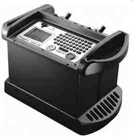
FIG. 19 Megger DLRO 200. (Courtesy of Megger, Inc., Valley Forge, PA.)
4.6 Circuit Breaker Time-Travel Analysis
This test is usually performed on MV and HV circuit breakers, usually 34 kV and above, to detect problems in the breaker operating mechanism. This test can be conducted with a mechanical or electronic time-travel analyzer.
Today, the electronic time-travel analyzers are replacing the old mechanical time-travel analyzers. With either analyzer information on the breaker operating mechanism is provided in form of charts or graphs which can be used to assess the mechanical and electrical condition of the breaker. There are nine tests that are usually conducted on the breaker with the circuit breaker analyzer. These tests are (1) closing time and opening time, (2) contact bounce, (3) opening and closing synchronization, (4) closing and opening speed (velocity and displacement), (5) trip operation, (7) trip-free operation, (8) close operation, and (9) trip-close operation.
Closing and opening time: In the example below, the closing time of the contacts is shown to be 31.4 ms (phase A), 30.2 ms (phase B), and 31.8 ms (phase C).
Also closing times of a breaker can be viewed in a graph form as displayed in FIG. 20.
Contact bounce: If we expand the x-axis in FIG. 20, we can actually view the contact bounce associated with the above breaker operation as shown in FIG. 21.
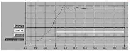
FIG. 20 Graph showing closing time of contacts of a breaker. (Courtesy of
Megger/Programma, Valley Forge, PA.)

FIG. 21 Graph showing contact bounce of a breaker. (Courtesy of Megger/Programma,
Valley Forge, PA.)
It is clear to see that there is 0.8 ms bounce associated with the contact movement in phase C. These series of contact bounces can be compared with future tests to see if there is any degradation to the actual mechanism associated with breaker contacts.
Opening and closing synchronization: The breaker opening and synchronization can be viewed as a group, i.e., the operation of all three phases together for breaker open and close cycle. This information will indicate whether the breaker contacts open and close together or how far apart the three-phase contacts are relative to each other during the close and open cycle as shown in the example below. The normal maximum time difference between all three phases should not be more than 2 ms for most breakers.
010 Diff A - B - C 1.6 ms
The synchronization of a breaker is defined as the time difference between the fastest and slowest phase (contact make and break) during the breaker open and close operation.
Total opening and closing speed: All breakers have specific speed, opening and closing times; therefore, it is important that breakers operate within their opening and closing time. For example, if a breaker is slow to open due to ageing or degradation, it may compromise the protect ion and coordination scheme of the protective relays, and thereby cause unwanted power interruption and equipment damage. Further, all breakers have specified closing speed which is defined as the average speed calculated between two defined points on the motion curve as indicated below.
016 Cls speed 8.40 m/s
These two points will be specified by the breaker manufacturer and define where to set both points for accurate speed measurements. For example, they will define the first point to be set to a distance above the open position and a distance below the upper point where the contact motion stops as indicated below.
Upper point Lower point
Distance above open position 80.0 mm Distance below upper point 20.0 mm Distance below closed position 10.0 mm Distance below upper point 10.0 mm Trip operation: The trip operation of a breaker is another name for an open operation. Most utility companies and plant owners want to perform a trip (or open) operation to monitor the speed of the opening mechanism and contacts to make sure there is enough energy in the spring mechanism to open under a fault condition. The graph for a trip is similar to the one for a close operation, except the motion of the mechanism is going in the opposite direction, i.e., from closed contacts to fully open position as seen in FIG. 22.
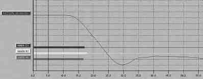
FIG. 22 Graph showing speed of the contacts opening for trip (or open) operation
of a breaker. (Courtesy of Megger/Programma, Valley Forge, PA.)

FIG. 23 Graph showing trip-free operation of a breaker. (Courtesy of Megger/Programma,
Valley Forge, PA.)
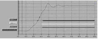
FIG. 24 Graph showing close operation of a breaker. (Courtesy of Megger/Programma,
Valley Forge, PA.)
Trip-free operation: This operation simulates the condition when an open breaker is closed into a fault and then it is tripped free by a protective relay.
Trip-free is an operation where the breaker contacts are in the open position and the breaker is operated to perform a close-open sequence. In this operation, the breaker is closed and then immediately sent a control command to open. This operation confirms whether a breaker, if closed into a fault, can clear it. The graph for a trip-free operation is shown in FIG. 23.
Close operation: This test is performed to verify a breaker's closing mechanism. The graph for close operation of a breaker is shown in FIG. 24 which is similar to the graph of FIG. 20.
Trip-reclose operation: In this test, the reclose operation of the breaker is checked to assure that the breaker closing time is within specified limits after a trip operation. The reclose time is measured either in milliseconds or cycles. The trip-reclose operation of the breaker is shown in FIG. 25.
The problems usually detected with this test are faulty dashpots, faulty adjustments, weak accelerating springs, defective shock absorbers, buffers and closing mechanisms, or broken parts. This test should be performed during acceptance tests and then during maintenance tests about every 3 years.
The breaker opening and closing parameters can easily be measured with a Megger Programma EGIL breaker analyzer or its equivalent manufactured by other vendors. The EGIL is designed to test MV breakers that have a common operating mechanism and a single break per phase. All three phases can be tested at the same time giving both individual phase timing and combined measurements for all three phases. The EGIL analyzer is shown in FIG. 26.

FIG. 25 Graph showing trip-reclose operation of a breaker. (Courtesy of Megger/Programma,
Valley Forge, PA.)
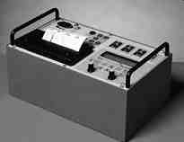
FIG. 26 The EGIL breaker analyzer. (Courtesy of Megger/Programma, Valley
Forge, PA.)
4.7 Dynamic Capacitance Measurement of HV Breakers
The latest trend in HV circuit breaker timing is DualGround testing using a method called dynamic capacitance measurement (DCM). DualGround is the trade name of Megger Programma, but other manufacturers making a similar instrument may call it Dual Earth testing. The DCM method can be explained as follows.
All HV circuit breakers exhibit the characteristics of a capacitive circuit when they are in the open state. As the breaker contacts start to move, the capacitance changes accordingly until the time at which they make contact and the circuit becomes a resistive circuit. The DCM test method measures the change in capacitance of the breaker during close cycle and quantifies it so it can be displayed with other breaker timing measurements. This DCM test may be performed with a full featured circuit breaker analyzer such as the Programma TM-1800 shown in FIG. 27.
The DCM method of breaker timing is primarily used for HV breakers, such as 220 kV and above. The test results of a DCM test are presented in the same manner as a normal breaker tests. A typical timing graph of a HV breaker is shown in FIG. 28.
This test method was developed to improve the safety of the test personnel in the HV substations. When using this method, safety grounds are placed on both sides of the breaker while performing the test as is shown in FIG. 29.
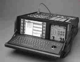
FIG. 27 The Programma TM-1800 for testing HV circuit breakers. (Courtesy
of Megger/Programma, Valley Forge, PA.)
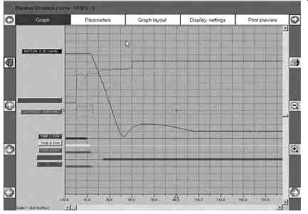
FIG. 28 Graph showing the breaker timing of a HV breaker. (Courtesy of Megger/Programma,
Valley Forge, PA.)
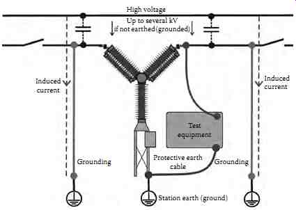
FIG. 29 Safety grounds being applied for testing of the HV breaker. (Courtesy
of Megger/Programma, Valley Forge, PA.)
By leaving both grounds in place while testing, an effective safe zone is created around the breaker for the test personnel. This will protect both the test equipment and more importantly protect the test personnel from any unwanted induced currents and voltages in the test circuit from adjacent energized lines.
5. Control Power for Switchgear
This section covers the requirements, selection, and maintenance of control power for MV switchgear.
5.1 Control Power Requirements
The requirements for any control power equipment are that it has sufficient capacity to deliver maximum power at rated voltage under all operating conditions. This can be particularly troublesome in locations where the incoming line voltages are subject to large fluctuations or where reliable control is needed for energizing a downstream piece of equipment that has an unusually large inrush current, or need to trip a breaker during a fault conditions.
Although standards are in place for circuit breaker close and trip coils, they do not cover many of the interposing devices that may be found in modern sequence and control schemes. The most important requirement of a control power source is that it must provide tripping power to circuit breakers. In addition to tripping power, it should also provide closing power. It is not uncommon to include other loads, such as indicating lamps, emergency lights, excitation power to synchronous motors, space heaters, fans, and remote lights, in the control power requirements. All these requirements must be considered when selecting a control power system.
Two main types of control voltages are used for MV switchgear: (1) DC control and (2) AC control. The source of DC control is storage batteries, whereas transformers are used for AC control. When AC control is used for closing, the tripping power is obtained from a capacitor trip device or a separate tripping battery. The choice between AC and DC control power depends on the following factors:
Number of circuit breakers in the switchgear
• Number of breakers operating simultaneously
• Number of auxiliary equipment connected
• Degree of reliability required
• Future expansion requirements
• Environmental conditions
• Maintenance of system
• Cost of the system
TABLE 9 NEMA Standard Voltages and Operating Ranges for Power Circuit Breakers
NEMA standards have established standard voltages and operating ranges for the switchgear circuit breakers, which are shown in Table 9.
5.1.1 Circuit Breaker Tripping
Power circuit breakers are equipped for manual tripping (pistol-grip handle or push button) and for electrically actuated tripping via a trip coil. The trip coil opens the breaker automatically when energized by a protective relay or manually by an operator via the manual handle. Tripping devices used for power circuit breakers are discussed as follows.
5.1.2 DC Battery Trip
The battery is probably the most reliable source of control power when it is properly maintained and serviced. It uses single contact protective relays to energize the breaker trip coil. It is unaffected by voltages and current during fault conditions. Generally, a 125 or 250 V battery is recommended for MV switchgear when both closing and tripping is required. When such is not available, a 48 V battery may be used for tripping only. However, it must be sized to meet the required load of the switchgear. A battery trip circuit is shown in FIG. 30a. Long service can be obtained from batteries when they are serviced regularly, fully charged, and the electrolyte level maintained at the proper level.
5.1.3 Capacitor Trip
The capacitor trip device is commonly used where a DC battery source is not available or uneconomical, such as in outdoor switchgear or where only few circuit breakers are installed. The capacitor device simply consists of a capacitor and half-wave rectifier charged from an AC control power transformer. When using a capacitor trip device, a separate capacitor trip unit is required for each breaker.
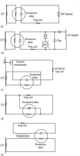
FIG. 30 Various methods of tripping for circuit breakers: (a) battery trip;
(b) capacitor trip device; (c) AC shunt trip coil, (d) circuit opening relays;
and (e) tripping transformer relay.
The capacitor trip device comes in two types: nonautocharge and autocharge.
The nonautocharge retains adequate charge for a short time (about 30 s) after the AC supply is lost. The autocharge consists of a regulated charge. It contains a voltage amplifier, a battery, and a battery charger. In case of loss of AC supply, the voltage amplifier steps up the battery voltage to maintain an adequate charge of the capacitor for several days. The simple capacitor trip device circuit is shown in FIG. 30b.
5.1.4 AC Methods of Tripping
The AC methods of tripping are used when sufficient current is always available during fault conditions. The tripping energy is obtained from the faulted circuit via the current transformers. This tripping is always associated with overcurrent protection. A potential trip coil is provided for each breaker for normal switching operations through a breaker control switch. The following AC trips are used in switchgear:
- AC shunt trip
- Circuit opening relays
- Tripping transformers
In the AC tripping schemes, three AC trip coils are used, one in each phase to ensure that under all fault conditions the breaker will have adequate cur rent to trip. The AC trip circuits are shown in FIG. 30c through e.
FIG. 31 Basic control closing methods of circuit breakers: (a) DC battery close; (b) 230 V close; (c) 230 V close; (d) manually close; (e) DC battery close; and (f) AC rectifier close.
5.1.5 Circuit Breaker Closing
The closing power for a circuit breaker can be either DC or AC voltage.
However, it is desirable to have closing power independent of voltage conditions on the power system. For this reason the DC battery is a preferable source of closing power. The choice may be dependent on economics, particularly where the switchgear consists of only a few circuit breakers or the investment in battery power could not be justified. The factors that influence the choice of closing power are the following:
Need to close breakers with power system de-energized
• Maintenance of the closing power
• Availability of space to house the control power equipment
• Degree of reliability required
• Expansion plans
All these factors must be considered in the evaluation of the closing power before a final decision is made on what equipment i s best suited for a particular installation. The following basic methods for closing power are available for switchgear applications:
1. Stored-energy mechanism
a. DC battery
b. 230 V control power transformer
c. 230 V lighting or power panel
2. Solenoid-operated mechanism
a. Manually (stored-energy close)
b. DC battery close
c. 230 V AC rectifier close
The basic methods of closing circuit breakers are shown in FIG. 31a through f. The current required for closing of stored-energy-mechanism breakers can be either DC or AC. The power required for the next close operation is stored in the springs with the preceding close operation of the breaker. The AC power must be present to initiate the control circuit to the spring-release solenoid for automatic close operation of the breaker. For non automatic operation, the spring release can be initiated manually. If needed, the stored-energy breaker close mechanism can be manually charged.
The AC source for solenoid breakers requires a separate closing rectifier for each breaker.
When selecting a control power source for breaker closing, the maximum closing load must be calculated. The number of breakers required for simultaneous closing must be known so that the system can provide the required energy.
In addition, any other loads that are connected to the system must be known.
The selection of control power involves the sizing and selection of DC battery and AC control power transformer equipment.