AMAZON multi-meters discounts AMAZON oscilloscope discounts
4. Fuses
Two basic families of fuses are current limiting and noncurrent limiting.
The current-limiting fuse melts and extinguishes the arc in a half-cycle or less. The noncurrent-limiting type may melt in less than a half-cycle when subjected to very high values of short-circuit current, but is unable to extinguish the arc in a half-cycle. Since the arc is a flexible conductor, the noncurrent-limiting-type fuse will allow the short-circuit current to reach its maximum peak value. The current-limiting type of fuses are constructed with mechanisms to extinguish the arc, thereby preventing the short-circuit cur rent from reaching its maximum peak value. The fuses are used in conjunction with circuit breakers, motor starters, disconnect switches, and the like to provide protection similar to the circuit breaker overcurrent trip devices.
However, fuses have fixed time-current relationships and therefore do not provide the same flexibility as the overcurrent relationships and therefore do not provide the same flexibility as the overcurrent trip devices. Fuses cannot open and close a circuit by themselves. They must be combined with some supplementary device, such as a disconnect switch, a circuit breaker, or a contactor. Fuses can be divided into medium- and low-voltage fuses.
4.1 Low-Voltage Fuses
Low-voltage fuses are divided into four broad categories:
1. Cartridge fuses, designed for the protection of circuits
2. Plug fuses, designed for the protection of circuits
3. Supplementary fuses, designed for the protection of small appliances, electronic equipment, and the like
4. Special fuses, designed for the protection of electrical equipment such as capacitors, welders, and rectifiers
The standards applicable to these fuses are NEMA FU-1 dated 2002, and ANSI/UL 248-1 through 248-15 dated 2000. In particular, the ANSI/UL 248-8 dated 2000 covers the class J fuses and ANSI/UL 248-10 dated 2000 covers class L fuses. Furthermore, UL has classified fuses as current limiting and non current limiting, as shown in Table 1. Further, classes R, J, L, T, and CC fuses are designated as branch circuit fuses suitable for protection of distribution systems, wiring, or equipment.
Because fuses are single-phase interrupters, they provide good protection for single-phase circuits. However, for multiphase circuits, these single-phase interrupters can cause problems such as single phasing, backfeeding, and ferroresonance. Single phasing can be detrimental to motors owing to the flow of negative-sequence currents, which can cause excessive heating of the motor rotor, causing motor failure or reducing its normal life. The degree of motor life reduction is a function of motor temperature and elapsed time between single-phase occurrence and motor de-energization.
The term back feeding is used to describe the condition when fault current continues to flow from the remaining energized phases, most probably at a reduced value owing to the additional impedance that has been inserted in the current path. The degree of fault current reduction will determine the time of response of the fuses in the remaining phases. As fuse interrupting time increases, the degree of damage also increases. Today's switchgear designs employing fuses as overcurrent protective devices use anti-single phase protection features. The anti-single phase feature in the fused switch gear open all three phases due to a single fuse blowing, thereby averting the adverse effects of single phasing discussed earlier.
====
TABLE 1
Current and Noncurrent-Limiting Fuses
-- Noncurrent limiting
Plug fuses (Edison base, C and S) (ANSI/UL 248-11-2000) Voltage rating, 125 V AC Current rating, 0-30 A Interrupting rating, not more than 10,000 A Current limiting Class J (ANSI/UL 248-8-2000) Voltage rating, 600 V AC Current rating, 0-600 A Interrupting rating, 200,000 A sym Class K (K-1, K-5, and K-9) (ANSI/UL 248-9-2000) Voltage rating, 250-600 V AC Current rating, 0-600 A Interrupting rating, 50,000-200,000 Class T (ANSI/UL 248-15-2000) Voltage rating, 300 and 600 V AC Current rating, 0-600 A Interrupting rating, 200,000 A sym Class RK1 Voltage rating, 250-600 V AC Current rating, 0-600 A Interrupting rating, 200,000 A sym
Class H (248-6 & 7-2000) Voltage rating, 250 and 600 V AC Current rating, 0-600 A Interrupting rating, not more than 10,000 A Class L (ANSI/UL 248-10-2000) Voltage rating, 600 V AC Current rating, 601-6000 A Interrupting rating, 200,000 A sym Class R (ANSI/UL 248-12-2000) Voltage rating, 250 and 600 V AC Current rating, 0-600 A
Interrupting rating, 200,000 A sym Class G (ANSI/UL 248-5-2000) Voltage rating, 300 V AC Current rating, 0-60 A Interrupting rating, 200,000 A sym Class RK5 Voltage rating, 250-600 V AC Current rating, 0-600 A Interrupting rating, 200,000 A sym
Class CC (ANSI/UL 248-4-2000) C Voltage rating, 600 V AC Current rating, 0-30 A Interrupting rating, 200,000 A sym Class CA/CB (ANSI/UL 248-3-2000) Voltage rating, 300 or 600 V AC Current rating, CA: 0-30 A; CB: 0-60 A Interrupting rating, 200,000 A sym
Class C (ANSI/UL 248-2-2000) Voltage rating, 600 V AC Current rating, 0-1200 A Interrupting rating, 200,000 A sym
============
5 Disconnect Switches
Disconnect switches are commonly used in low- and medium-voltage systems. The application of disconnect switches can be divided into low- voltage (600 V and below) and medium-voltage (601 V through 15 kV) classes.
The medium-voltage switches are discussed in Section 7.
5.1 Low-Voltage Switches
Low-voltage switches can be classified into three broad categories: (1) isolating switches, (2) safety switches, and (3) interrupter switches. The isolating switch has no interrupting or load-carrying capability. It serves only to provide isolation of the circuit or load by manual means after the power flow is cut off by the circuit protective device.
The safety switch is a load-break switch having a quick-make and quick-break contact mechanism. Safety switches are used in small power systems with limited short-circuit capacity. The safety switch may be fused or unfused.
The interrupter switch is of quick-make, quick-break type and is capable of interrupting at least 12 times its continuous current rating. They are assigned horsepower rating. These switches are available in continuous rating from 30 to 1200 A and can be installed in switchboards, panelboards, and grouped motor control centers. The interrupter switch may be utilized with or without fuses depending upon the application.
Some light industrial systems or commercial buildings will use switchgear or switchboards with a high pressure or bolted pressure, three-pole switch acting as incoming service main disconnects. The principal feature of these switches is their continuous current capacities of up to 3000 or 4000 A. At these currents, very high contact pressure is required on the conducting surfaces in order to hold temperature rises to reasonable levels. The switches themselves carry an interrupting rating similar to those for three-pole interrupter switches but not as high as that for power circuit breakers. Interrupting capability for short circuits is almost always handled by current-limiting fuses, which are an integral part of the switch. Most manufacturers provide single phase, blown fuse, and ground fault accessories so that the switches can be used on low-voltage service entrances. Unlike trip devices applied to circuit breakers, these protective devices are not self- powered. Rather, they take operating voltage from a small control power transformer on the source side of the switch. Generally, the mechanical design of these switches is based on a minimum of operations. The number of operations is expected to be less than for insulated-case breakers; usually limited to isolation during maintenance or for serious ground faults not cleared successfully by other means.
6 Selection and Application of Low-Voltage Equipment
The modern distribution system has high short-circuit current available and therefore requires special consideration so that equipment may be applied within its rating. Furthermore, the switchgear should be protected against all types of faults, from low-level arcing faults to bolted faults. The protection system should be selective; that is, the fault at a remote location in the system should be localized without unnecessary tripping of either the main breaker system or any intermediate breakers. The distribution system should be planned to provide continuity and reliability of service. This can be achieved by using two or more separate distribution systems instead of one large system. The continuous current rating of the main protective device should be adequate for the load to be served. Protective devices should not be paralleled to obtain a higher rating. As a general rule, the bus bars are rated on the basis of not more than 800 A/in.^2 of aluminum or 1000 A/in.^2 of copper. The operation of protective devices is based upon an ambient temperature of 40 °C, and if these devices are to be applied at higher tempera ture, the manufacturer should be consulted. The short-circuit rating of a bus is limited to the interrupting rating of the lowest rated protective device, and the available short-circuit current should not exceed this value.
The application of circuit breakers and fuses must be considered to determine which offers the most appropriate protection. Consideration should be given to anti-single-phase devices when three-pole interrupter switches with fuses are used, because fuses are single-pole interrupter switches. An arcing fault may not be stopped by a single-pole interruption. It can be backfed from the other energized phases. Because of this condition, severe equipment burn downs may occur. Ferroresonance is the result of interaction between the reactance of a saturable magnetic device, such as a transformer, and system capacitance. Ferroresonance can also occur due to a single phasing condition.
This phenomenon occurs mostly in high- and medium-voltage systems and results in a very high voltage on the order of three to five normal system voltage which is imposed on the circuit involved, causing equipment failure.
Always keep in mind that fuses should be applied in systems where the system voltage is compatible with the fuse voltage rating. The reason for this is that the arc voltage generated by a fuse when interrupting is several times its voltage rating and, if misapplied, could subject the system to overvoltage conditions, causing equipment failure.
The current-limiting features of current-limiting fuses are definite strong pluses for many applications; however, use the fact wisely, for they do not limit current for all values of fault current. If the fault current magnitude is equal to or greater than the fuse threshold current, they will always be current limiting.
However, if the fault current magnitude is less than the fuse threshold current, but greater than the current magnitude indicated at the intersection of the maximum peak current curve and fuse curve, the fuse may or may not be cur rent limiting. For fault current magnitude indicated by the above curve intersection, the fuse is never current limiting.
For this reason and arc-voltage considerations, when applying current limiting fuses to increase the interrupting rating of other protectors, the fusing recommendations of the product manufacturers, not the fuse manufacturer, should be followed. Fused equipment can be opened and closed manually or electrically to provide circuit protection. However, the fuse and equipment should be coordinated and tested as a combination. The fuse's adequate performance as a circuit protector and switching device should be certified by one manufacturer.
When fused switches are electrically controlled, caution is required not to let the switch open due to fault conditions. The fault current, if not sufficient to cause interruption before the switch contacts or blades open, could be greater than the contacts' or blades' interrupting capability. This would result in a hazardous condition. Fused switches basically require the same application considerations as previously outlined in this section.
Fused motor starters applied in medium- and low-voltage systems avoid the ferroresonance problem owing to their location in the system. Auxiliary devices can be supplied with motor starters to provide a complete overload protection and anti-single-phasing protection. The selection and application of switchgear should be approached on an engineering basis. To provide reliability, ease of maintenance, and continuity of service, properly rated equipment and adequate circuit protection are necessary throughout the entire system, from the place where the power system enters the facility down to the smallest load.
6.1 Assessing Service Life of Low-Voltage Breakers
The National Electrical Manufacturers Association (NEMA), American Standards National Institute (ANSI), and Institute of Electrical and Electronic Engineers (IEEE) standards for low-voltage power circuit breakers and MCCBs contain performance criteria for assessing the service life of manufactured products. The pertinent industry standards for low-voltage breakers are ANSI/ IEEE C37.16-2000, C37.26-2003, C37.50-2000, C37.51-2003, NEMA AB-1-2002, and AB-4-2003. In addition, the MCCBs are tested at the manufacturer's production facility and/or at UL facilities in accordance with standards promulgated by the industry and UL-489-2002. The performance criteria contained in these standards can also help users anticipate the need for maintenance testing, inspections, refurbishment, and/or replacement of the manufactured products. This section provides an overview of the requirements covered in the referenced industry standards and the methods typically used by manufacturers in making the products. It is expected that an understanding of the endurance requirements covered in the standards should provide insights that can be used to inspect and evaluate the health for continued reliable operation (i.e., the service life) of low-voltage power circuit breakers and MCCBs. There are four basic electrical ratings and endurance requirements for switchgear components and assemblies such as circuit breakers.
6.1.1 Maximum Voltage Rating or Nominal Voltage Class
Low-voltage power circuit breakers are marked with the maximum system voltage at which they can be applied. Standard maximum voltage ratings are 635, 508, and 254 V for application of the breakers in 575, 480, and 208 V electrical power systems, respectively. A low-voltage breaker can be used in a circuit that has a nominal voltage rating less than the breaker's maximum voltage rating. For example, a 635 V rated circuit breaker can be applied in a 208, 240, 480, or 600 V rated circuit. For fused breakers, the 635 V maximum voltage rating becomes 600 V to match the voltage rating of the fuses.
6.1.2 Continuous Current Rating
The continuous current rating of a circuit breaker, isolator switch, load-break switch, switchgear assembly, or motor control center is the number of amperes; that the device can carry continuously without the temperature of any insulation component becoming greater than its rated temperature. For low-voltage power circuit breakers and MCCBs, the continuous current rating of the breaker's frame is called the frame size. For any low-voltage power circuit breaker that can accept a replaceable trip device, installation of a trip device that has a continuous current rating that is less than the frame size reduces the continuous rating of the circuit breaker. It is not permissible to install a trip device that has a continuous current rating that is greater than the breaker's frame size.
6.1.3 Rated Short-Circuit Current (Circuit Breakers)
Low-voltage circuit breakers are designed and manufactured with one or more interrupting ratings (rated short-circuit current), often called interrupting ampere capability (AIC). These interrupting ratings are the maximum values of available (prospective) short-circuit current (fault) that the breaker is able to interrupt (short-circuit duty cycle) at different maxi mum voltage values. Available current is defined in the industry standards as the expected rms symmetrical value of current at a time one half-cycle after short-circuit initiation. The maximum fault in a power system occurs at one half-cycle time. The low-voltage breakers are fast acting and begin to part contacts at about one half-cycle time which is point of maximum short circuit current. Therefore, as the breaker contacts begin to part, i.e., as the breaker begins to interrupt the short-circuit current it is subjected to the maximum asymmetrical current. The asymmetry of the short-circuit current is a function of the X/R ratio, or the power factor of the short-circuit current.
The ANSI/UL standard 489, "Standard for molded case circuit breakers and circuit breaker enclosures" along with AB-1 contain the criteria for performing interrupting ability tests for molded-case breakers. These standards specify the power factor of the test circuit with the required current flowing that is to be used for establishing the asymmetry of the short-circuit current.
The NEMA AB-1-2002 and UL 489-2002 standards have established three asymmetry categories (i.e., power factor) of short-circuit current interrupting capabilities. The three asymmetry categories (short-circuit current and power factor) given in NEMA AB-1 and UL 489 are shown in first two columns of Table 2. The associated X/R ratio and the accompanying multiplying factors are shown in columns 3 and 4 of Table 2. What the UL 489 and relevant
industry standards are saying is that the asymmetry is greater for fault cur rents at the locations where the short- circuit current is high, and it is smaller at locations where the short-circuit current is less. Another way of stating this criterion is to say that the breakers applied closer to the substations will experience higher short-circuit currents with higher asymmetry in the fault current, thereby subjecting a breaker to undergo a higher short-circuit duty while interrupting the fault. The opposite is true for breakers applied further away (downstream) from the substation because such breakers will see lower short-circuit currents and lower asymmetry in the short-circuit current.
TABLE 2 Power Factor of Test Circuits-NEMA-AB-1-2002 and UL-489-2002
TABLE 3 Preferred Short Circuit Ratings in rms Symmetrical Amperes
What this all means is that power factor is lower (or X/R ratio is higher) near the substations and power factor is higher (or X/R ratio is lower) further away from the substation. It should be noted that the maximum asymmetry for the low-voltage circuit breakers is capped at power factor of 0.15, X/R ratio of 6.6.
However, examination of the manufacturer and UL data shows that most breakers are tested at a maximum power factor of 0.20 or X/R ratio of 4.87. The low-voltage breaker's short- circuit interrupting capability is indicated in sym metrical amperes since the asymmetry is already included in the test circuit current when the breakers are tested for interrupting capability. Also, note that the short circuit duty cycle is a specific test that is performed on a prototype model of a circuit breaker. A detailed explanation of this test can be found in ANSI/IEEE standards C37.16, C37.50, UL 489, and NEMA AB-1. Table 3 shows the interrupting symmetrical ampere capabilities published in NEMA AB-1 for the breakers manufactured by NEMA member companies.
Each model of circuit breaker can have a different set of interrupting current capabilities listed in Table 3. The interrupting capability of a low voltage breaker varies with the applied voltage. For example, a 1600 A-rated breaker applied at 240 V might have an interrupting capability of 65 kA at 240 V, whereas the same breaker applied at 480 V would have an interrupting capability of 50 kA. The interrupting capability also changes if the breaker's automatic trip device has a short-time trip function rather than an INST trip function. For example, a 4000 A-rated circuit breaker that has an INST trip might have an interrupting capability of 150 kA at 240 V, whereas the same breaker equipped with a short-time trip has an interrupting capability of 85 kA at 240 V. Any low-voltage power circuit breaker that is equipped with current limiting fuses (current limiters) has short-circuit current rating equal to 200 kA. Rated short-circuit current is also influenced by the ability of a circuit breaker to close and latch against, carry, and subsequently interrupt, a fault current.
Breakers have closing and latching capabilities, sometimes called momentary rating, relate to the breaker's ability to withstand the mechanical and thermal stress of the first half-cycle of a fault current, i.e., asymmetrical short-circuit current. Low-voltage power circuit breakers and MCCBs display no nameplate information concerning momentary rating. These types of breakers are traditionally tested and applied according to their interrupting current capability in RMS amperes. The reason that momentary ratings do not appear on their nameplates is that these breakers are tested with the asymmetry already included in the symmetrical amperes of the test circuit that was discussed earlier. For those few system applications that have a greater asymmetrical value than the asymmetry of test circuit current (i.e., X/R = 6.6), a circuit breaker of higher interrupting current rating should be applied.
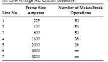
TABLE 4 Overload Switching Requirements for Low-Voltage AC Circuit Breakers
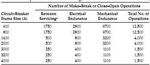
TABLE 5 Endurance Requirements for Low-Voltage AC Power Circuit Breakers
6.1.4 Short-Circuit Current Ratings-Panelboards, MCCs, and Switchgear Assemblies
A panelboard has a short-circuit current rating shown on its nameplate. A panelboard is not allowed to be applied in any circuit whose available fault cur rent is greater than its short-circuit current rating. The short-circuit current rating of a panelboard is limited to the lowest value of rated short-circuit current for any circuit breaker that is installed within the panelboard. The short circuit withstand rating of a motor control center is the average rms current that its busses can carry for 2s. A motor control center is not allowed to be applied in any circuit whose available fault current is greater than its short-circuit withstand rating. The rated momentary current of metal-enclosed or metal-clad switchgear represents the maximum rms current that it is required to withstand during a test of 10 cycles duration.
This test is conducted on a prototype model. The rated short-time current of metal- enclosed or metal-clad switchgear is the average rms current that it can carry for a period of 2 s.
6.1.5 Endurance Requirements for Low-Voltage Breakers
The ANSI/IEEE standard for switchgear C37.16-2000 provides endurance requirements of low-voltage power circuit breakers and AC power circuit protectors. Although primarily used by manufacturers who have an interest in assuring a durable product, these endurance requirements can also help equipment users to anticipate the need for maintenance or replacement.
In order to verify that a particular design of circuit breaker meets the endurance requirements, a manufacturer performs all endurance tests on a single circuit breaker. Table 4 appears in the standard and represents the number of times that the circuit breaker is required to make and subsequently break line currents that are 600% of the breaker's rated continuous current. The test method includes specifications for how much time can elapse between switching operations. The breaker components that are most likely to become worn during this endurance test are arcing tip and arc chutes.
Table 5 also appears in the ANSI 37.16-2000 and represents the number of open-close or close-open operations that the breaker's operating mechanism is required to endure when making and breaking 100% of its rated current (electrical endurance) and no current (mechanical endurance). The components that are most likely to become worn during this endurance test are latches, cam, rollers, bearings, pins, clamps, and threaded hardware.
In order to pass this test, adjusting, cleaning, lubricating, and tightening are allowed at the intervals shown in column 2 of Table 5. The numbers in this column contain a clear implication that maintenance is required in order to allow a circuit breaker's operating mechanism to realize its full lifetime.
An examination of the Annex A ANSIC37.16-2000 reveals several comments that relate strongly to breaker maintenance. These comments are:
(1) The circuit breaker should be in a condition to carry its rated continuous current at maximum rated voltage and perform at least one opening operation at rated short- circuit current. After completion of this series of operations, functional part replacement and general servicing may be necessary, (2) If a fault operation occurs before the completion of the listed operations, servicing may be necessary, depending on previous accumulated duty, fault magnitude, and expected future operation, (3) Servicing consists of adjusting, cleaning, lubricating, tightening, and the like, as recommended by the manufacturer. When current is interrupted, dressing of contacts may be required as well. As indicated in the standards, the breaker operations listed for endurance are based on servicing at intervals of 6 months or less.
The implication for maintenance is that a power circuit breaker might not be suitable for continued service after it has interrupted a fault current at or near its short-circuit current rating. Unless the magnitude of a fault current is known to have been significantly less than rated short circuit value, it is good practice to perform a physical inspection on a breaker before it is used to reenergize a power circuit. Physical inspections at periodic maintenance intervals will reveal wear of components and parts before a circuit breaker looses its ability to interrupt an overload current or a fault. For circuit breakers that are equipped with a monitoring system, the number of overload operations can be automatically recorded in a data log that can subsequently be analyzed to determine whether a circuit breaker is in need of an inspection.
The requirements for conducting endurance tests for MCCBs are given in NEMA AB-1 and UL-489 and the criteria differ somewhat from the ANSI C37.16 requirements. The categories of electrical operations are referred to as operation with current and the mechanical tests are referred to as operation without current. The requirements for the endurance tests for MCCB are shown in Table 6.
====
TABLE 6 Endurance Requirements for MCCBs Number of Make-Break or Close-Open Operations
Source: From UL-489-1991, Standard for Safety Molded-Case Circuit Breakers, Molded-Case Switches, and Circuit-Breaker Enclosures.
a. For circuit breakers rated more than 800 A, the endurance test may, at the option of the manufacturer, be conducted in groups of 100 load operations. No-load operations may be conducted between groups of load operations at the option of the manufacturer.
b. Where tests are required on samples having ratings of 100 A or less, 250 V or less, the number of operations is to be the same as for the 100 A frame.
c. Rate of operation: 1 cycle per minute for first 10 operations; thereafter in groups of 5, at 1 cycle per minute, with an interval between groups that is agreeable to the submitter and the testing agency.
====