AMAZON multi-meters discounts AMAZON oscilloscope discounts
6.3.5 Measurements at the Transformer
Transformers are subject to overheating from harmonic currents. Transformers supplying nonlinear loads should be checked periodically to verify operation is within acceptable limits. Transformers are also critical to the integrity of the grounding system. TBL. 12 lists the various measurements needed for transformers.
=====
TBL. 12
Measurements at the Distribution Transformer Measurement Look for Instrument
1. kVA Transformer loading. If loading exceeds 50%, check for harmonics and possible need for derating Three-phase or single-phase analyzer
2. Harmonic spectrum 1. Harmonic orders/amplitudes present: third harmonic (single-phase loads), fifth, seventh (primarily three-phase loads) Same
2. Resonance of higher order harmonics
3. Effectiveness of harmonic trap filters
3. THD Harmonic loading within limits: voltage
%THD <5%, current %THD <5%-20% Same
4. K-factor Heating effect on transformer from harmonic loads Same
5. Ground currents 1. Objectionable ground currents are not quantified but are prohibited by the NEC Same and true-rms clamp-on multimeter
2. N-G bond in place
3. Electrical safety ground (ESG) connector to ground electrode (typically building steel) in place
=====
Measurements:
Transformer loading (kVA): If the transformer has a four-wire wye secondary, which is the standard configuration for commercial single-phase loads, actual kVA can be easily determined by measuring phase currents supplied from each winding and then calculating each kVA, or measuring directly the kVA in each phase. The sum of individual phase kVA then gives the three-phase kVA of the transformer. Compare actual load kVA measured or calculated against nameplate kVA rating to determine % loading. If the load is balanced, a single measurement is sufficient. Transformers loaded at less than 50% are generally safe from overheating. However, as loads increase, measurements should be made periodically. At some point the transformer may require de-rating because of nonlinear loading.
Harmonic spectrum: The harmonic spectrum of the secondary (load) current will give an idea of the harmonic orders and amplitudes present:
In a transformer feeding single-phase loads, the principal harmonic of concern is the third. The third will add arithmetically in the neutral and circulate in the delta primary of a delta-wye transformer. The delta-wye connected transformer tends to isolate the rest of the system from the third harmonic currents from the primary system, however it does isolate the fifth, seventh or other non-triplen harmonics. The third harmonic and triplen harmonic current however will cause additional heating of the transformer.
In a transformer feeding three-phase loads which include drives or UPS systems with six-pulse converters, the fifth and seventh harmonic will tend to pre dominate. Excessive fifth is of particular concern because it’s negative sequence.
It will tend to produce counter-torque and overheating in polyphase motors.
Harmonic amplitudes normally decrease as the harmonic frequency goes up. If one frequency is significantly higher in amplitude than lower frequencies, we can suspect a resonant condition at that frequency. If such a condition is detected, be sure to take readings at capacitor banks to see if the caps are experiencing overcurrent/overvoltage conditions.
Before-and-after harmonic spectrum measurement is extremely valuable to determine if harmonic mitigation techniques, like trap filters, which are tuned to specific frequencies, are sized properly and are working as expected. Different harmonic frequencies affect equipment in different ways. See TBL. 13 for harmonic sequences and their effects on equipment.
====
TBL. 13
(a) Harmonic Frequencies, Sequences, and (b) Effects Name First Second Third Fourth Fifth Sixth Seventh Eighth Ninth (a) Harmonic frequencies and sequences Frequency 60 120 180 240 300 360 420 480 540 Sequence + - 0 + - 0 + - 0 Sequence Rotation Effects (from skin effect, eddy current etc.) (b) Effects of harmonic sequences Positive Forward Heating of conductors, circuit breakers, etc.
Negative Reverse Heating as above + motor heating and problems Zero None Heating of the neutral conductor, bus and transformer neutral Rule: If waveforms are symmetrical, even harmonics disappear.
Harmonics are classified as follows:
1. Order or number: Multiple of fundamental, hence, third is three times the fundamental, or 180 Hz.
2. Odd or even order: Odd harmonics are generated during normal operation of non linear loads. Even harmonics only appear when there is DC in the system. In power circuits, this only tends to occur when a solid-state component(s), such as a diode or SCR, fails in a converter circuit.
3. Sequence:
a. Positive sequence. Main effect is overheating.
b. Negative sequence. Create counter-torque in motors, i.e., will tend to make motors go backwards, thus causing motor overheating. Mainly fifth harmonic.
c. Zero sequence. Add in neutral of three-phase, four-wire system. Mainly third harmonic.
====
THD: Check for THD of both voltage and current:
For voltage, THD should not exceed 5%. For current, THD should not exceed 5%-20%.
IEEE 519 sets limits for harmonics at the point of common coupling (PCC) between the utility and customer (EN50160 is the European standard that is equivalent to the IEEE 519). IEEE 519 addresses THD measurements that are taken at the PCC which is usually considered to be the main transformer between the utility and the customer. Therefore the THD measurements are often made at the secondary of the customer's main transformer, since that is the point most easily accessible to all parties. Some PQ practitioners have broadened the concept of PCC to include points inside the facility, such as on the feeder system, where harmonic currents being generated from one set of loads could affect another set of loads by causing significant voltage distortion. The emphasis is on improving in-plant PQ, rather than on simply not affecting utility PQ.
Voltage THD: THD has a long history in the industry. The underlying concept is that harmonic currents generated by loads will cause voltage distortion as they travel through the system impedance. This voltage distortion then becomes the carrier of harmonics system wide. If for example, the distorted voltage serves a linear load like a motor, it will then create harmonic currents in that linear load. By setting maximum limits for voltage distortion, we set limits for the system-wide impact of harmonics.
Voltage distortion, however, depends on source impedance, i.e., on system capacity. It’s quite possible for the first (or second or third) customer to inject significant harmonic currents into the system and not cause voltage THD to exceed 5%. The entire responsibility for harmonic mitigation could fall on the last customers unlucky enough to push volt age THD over 5%, even if their particular harmonic load was relatively small.
TBL. 14 IEEE 519 Limits for Harmonic Currents at the PCC
Current THD: To restore some fairness to this situation, standards for maxi mum current harmonics were added, since current harmonics were under the control of the local facility and equipment manufacturer (remember, harmonic loads act as generators of harmonics). This emphasis on the mitigation of current harmonics at the load, including the not-too-distant requirement that the load generate virtually no harmonics, has become the prevailing regulatory philosophy. It puts the burden of responsibility on the local site and on the equipment manufacturers. For equipment manufacturers, EN50160, IEC/EN 61010, and IEC/EN 61000-4, are the applicable European standards. To meet requirement for the European market, USA manufacturers will have to meet the above listed standards. The limits set in IEEE 519 for harmonic currents depend on the size of the customer relative to the system capacity. The SCR is a measure of the electrical size of the customer in relation to the utility source. The smaller the customer (higher SCR), the less the potential impact on the utility source and the more generous the harmonic limits. The larger the customer's power system (smaller SCR), the more stringent the limits on harmonic currents. Refer to TBL. 14 for current harmonic limits at the PCC.
Total demand distortion (TDD) and THD: TDD is the ratio of the current harmonics to the maximum load (IL). It differs from THD in that THD is the ratio of harmonics to the instantaneous load. Why TDD instead of THD? Suppose you were running a light load (using a small fraction of system capacity), but those loads were nonlinear. THD would be relatively high, but the harmonic currents actually being generated would be low, and the effect on the supply system would in fact be negligible. Therefore, TDD allows harmonic load to be referenced to the maximum load: if harmonic load is high at maximum load, then we have to watch out for the effect on the supply source. So where does that leave current THD as a useful measurement. The closer the current THD reading(s) is taken to conditions of maximum load, the closer it approximates TDD. The one place not to apply the specs is at the individual harmonic-generating load. This will always be a worst-case distortion and a misleading reading. This is because as
harmonics travel upstream, a certain amount of cancellation takes place (due to phase relationships which, for practical purposes, is difficult to predict). THD and TDD should be measured at a PCC, or at the source transformer.
K-factor: K-factor is a specific measure of the heating effect of harmonics in general and on transformers in particular. It differs from the THD calculation in that it emphasizes the frequency as well as the amplitude of the harmonic order. This is because heating effects increase as the square of the frequency.
A K-4 reading would mean that the stray loss heating effects are four times normal. A standard transformer is, in effect, a K-1 transformer. As with THD, it’s misleading to make a K-factor reading at the load or receptacle because there will be a certain amount of upstream cancellation; transformer K-factor is what counts. Once the K-factor is determined, choose the next higher trade size. K-factor rated transformers are available in standard trade sizes of K-4, K-13, K-20, K-30, etc. K-13 is a common rating for a transformer supplying office loads. The higher ratings tend to be packaged into power distribution units (PDUs) which are specially designed to supply computer and other PQ sensitive installations. For additional information on K-rated transformer, refer to Section 5.2.1.
Ground currents: Two prime reasons for excessive ground current are illegal N-G bonds (in subpanels, receptacles, or even in equipment) and so-called IG rods:
Subpanel N-G bonds create a parallel path for normal return current to return via the grounding conductor. If the neutral ever becomes open, the equipment safety ground becomes the only return path; if this return path is high impedance, dangerous voltages could develop.
Separate IG rods almost always create two ground references at different potentials, which in turn cause a ground loop current to circulate in an attempt to equalize those potentials. A safety and equipment hazard is also created: in the case of lightning strikes, surge currents traveling to ground at different earth potentials will create hazardous potential differences.
Transformer grounding: The proper grounding of the transformer is critical.
NEC Article 250 in general and 250-26 in particular address the grounding requirements of the separately derived systems (SDS).
A ground reference is established by a grounding connection, typically to building steel (which, in turn, is required to be bonded to all cold water pipe, as well as to any and all earth grounding electrodes). Bonding should be by exothermic weld, not clamps that can loosen over time. The grounding electrode conductor itself should have as low a high-frequency impedance as possible (not least because fault current has high frequency components). Wide, flat conductors are preferred to round ones because they have less inductive reactance at higher frequencies. For the same reason, the distance between the grounding electrode conductor connection to the system (i.e., N-G bond at the transformer) and the grounding electrode (building steel) should be as short as possible.
The neutral and ground should be connected at a point on the transformer neutral bus. Although permitted, it’s not advisable to make the N-G bond at the main panel, in order to maintain the segregation of normal return cur rents and any ground currents. This point at the transformer is the only point on the system where N-G should be bonded. Refer to TBL. 15 for inspection of the transformer grounding related to PQ problems.
====
TBL. 15
Inspection of the Transformer Grounding for PQ Problems
Inspection of Transformer Ground Explanation Check for N-G bond A high impedance N-G bond will cause voltage fluctuation Check for grounding conductor and integrity of connection to building steel (exothermic weld) Fault currents will return to the source via these connections, so they should be as low impedance as possible Check for tightness of all conduit connections If the conduit is not itself grounded, it will tend to act as a choke for higher frequencies and limit fault current (remember that fault currents are not just at 60 Hz but have high-f components) Measure for ground currents on the grounding conductor Ideally there should be none, but there will always be some ground current due to normal operation or leakage of protective components (MOVs, etc.) connected from phase or neutral to ground.
However, anything above an amp should be cause for suspicion (there is no hard and fast rule, but experienced PQ troubleshooters develop a feel for possible problems)
====
Solutions: There are a number of solutions for transformer-related PQ problems. They are Install additional distribution transformers
• Derate transformers
• Install K-rated transformers
• Used forced air cooling
SDS: The distribution transformer is the supply for a SDS, a term which is defined in the NEC (Article 100). The key idea is that the secondary of this transformer is the new source of power for all its downstream loads: this is a powerful concept in developing a PQ distribution system. The SDS accomplishes several important objectives, all beneficial for PQ:
It establishes a new voltage reference. Transformers have taps which allow the secondary voltage to be stepped up or down to compensate for any voltage drop on the feeders.
It lowers source impedance by decreasing, sometimes drastically, the distance between the load and the source. The potential for volt age disturbances, notably sags, is minimized.
• It achieves isolation. Since there is no electrical connection, only magnetic coupling, between the primary and secondary, the SDS isolates its loads from the rest of the electrical system. To extend this isolation to high frequency disturbances, specially constructed isolation transformers provide a shield between the primary and secondary to shunt RF noise to ground. Otherwise, the capacitive coupling between primary and secondary would tend to pass these high-frequency signals right through.
• A new ground reference is established. Part of the definition of the SDS is that it "has no direct electrical connection, including a solidly connected grounded circuit conductor, to supply conductors originating in another system." (NEC 100) The opportunity exists to segregate the subsystem served by the SDS from ground loops and ground noise upstream from the SDS, and vice versa.
K-rated transformers: Harmonics cause heating in transformers, at a greater rate than the equivalent fundamental currents would. This is because of their higher frequency. There are three heating effects in transformers that increase with frequency Hysteresis:
• When steel is magnetized, magnetic dipoles all line up, so that the north poles all point one way, the south poles the other. These poles switch with the polarity of the applied current.
The higher the frequency, the more often the switching occurs, and, in a process analogous to the effects of friction, heat losses increase.
Eddy currents:
• Alternating magnetic fields create localized whirl pools of current that create heat loss. This effect increases as a square of the frequency. For example, a third harmonic current will have nine times the heating effect as the same current at the fundamental.
Skin effect
• . As frequency increases, electrons migrate to the outer surface of the conductor. More electrons are using less space, so the effective impedance of the conductor has increased; at the higher frequency, the conductor behaves as if it were a lower gauge, lower ampacity, higher impedance wire. The industry has responded with two general solutions to the effects of harmonics on transformers: install a K-factor rated transformer or derate a standard transformer.
Let us look at pros and cons of the K-factor approach first. K-factor is a calculation based on the rms value, %HD of the harmonic currents, and the square of the harmonic order (number). It’s not necessary to actually perform the calculation because a harmonic analyzer will do that for you. The important thing to understand is that the harmonic order is squared in the equation and that is precisely where the high frequency heating effects, like eddy current losses, are taken into account. K-rated transformers are designed to minimize and accommodate the heating effects of harmonics. K-rated transformers don’t eliminate harmonics (unless additional elements like filters are added).
They accommodate harmonics with techniques such as the use of a number of smaller, parallel windings instead of a single large winding: this gives more skin for the electrons to travel on. The primary delta winding is up-sized to tolerate the circulating third harmonic currents without overheating. The neutral on the secondary is also up-sized for third harmonics (typically sized at twice the phase ampacity).
Application issues with K-factor transformers: K-rated transformers have been widely applied, but there are certain issues with them. Many consultants don’t see the need for using transformers with a rating higher than K-13 although K-20 and higher might be supplied as part of an integrated PDU. Also, early applications sometimes overlooked the fact that K-rated transformers necessarily have a lower internal impedance. Whereas a standard transformer has an impedance typically in the 5%-6% range, K-rated transformers can go as low as 2%-3% (lower as the K-rating increases). In retrofit situations, where a standard transformer is being replaced by a K-rated transformer of equivalent kVA, this may require new short-circuit calculations and resizing of the secondary overcurrent protective devices.
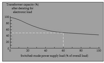 FIG. 23 Transformer derating curve (IEEE Std 1100-1992, IEEE Recommended
Practice for Powering and Grounding Sensitive Electronic Equipment.)
FIG. 23 Transformer derating curve (IEEE Std 1100-1992, IEEE Recommended
Practice for Powering and Grounding Sensitive Electronic Equipment.)
Derating standard transformers: Some facilities managers use a 50% derating as a rule-of thumb for their transformers serving single-phase, predominantly nonlinear loads. This means that a 150 kVA transformer would only supply 75 kVA of load. The derating curve (see FIG. 23), taken from IEEE 1100-1992 (Emerald Book), shows that a transformer with 60% of its loads consisting of SMPS, which is certainly possible in a commercial office building, should in fact be derated by 50%. The following is an accepted method for calculating transformer derating for single-phase loads only. It’s based on the very reasonable assumption that in single-phase circuits, the third harmonic will predominate and cause the distorted current waveform to look predictably peaked. Use a true-rms meter to make these current measurements:
1. Measure rms and peak current of each secondary phase. (Peak refers to the instantaneous peak, not to the inrush or peak load rms current).
2. Find the arithmetic average of the three rms readings and the three peak currents and use this average in step 3 (if the load is essentially balanced, this step is not necessary).
3. Calculate xformer harmonic derating factor:
xHDF = (1.414 * Irms)/Ipeak
4. Or, since the ratio of peak/rms is defined as CF, this equation can be rewritten as: xHDF = 1.414/CF
If the test instrument has the capability, measure the CF of each phase directly. If the load is unbalanced, find the average of the three phases and use the average in the above formula. Since a sine wave current waveform has a CF = 1.414, it will have an xHDF = 1; there will be no derating. The more the third harmonic, the higher the peak, the higher the CF. If the CF were 2.0, then the xHDF = 1.414/2 = 0.71. A CF = 3 gives us an xHDF = 0.47. A wave with CF = 3 is about as badly distorted a current waveform as you can expect to see on a single-phase distribution transformer.
Caution: This method does not apply to transformers feeding three-phase loads, where harmonics other than the third tend to predominate and CF is not useful as a simple predictor of the amount of distortion. A calculation for three-phase loads is available in ANSI/IEEE C57.110. However, there is some controversy about this calculation since it may underestimate the mechanical resonant vibrations that harmonics can cause, and that accelerate transformer wear above and beyond the effects of heat alone.
6.3.6 Electrical Noise
FIG. 24 Noise coupling. Ground noise measured as ø-G or N-G noise. (Fluke Corporation)
Electrical noise is the result of more or less random electrical signals get ting coupled into circuits where they are unwanted, i.e., where they disrupt information-carrying signals. Noise occurs on both power and signal circuits, but generally speaking, it becomes a problem when it gets on signal circuits. Signal and data circuits are particularly vulnerable to noise because they operate at fast speeds and with low voltage levels. The lower the signal voltage, the less the amplitude of the noise voltage that can be tolerated.
The signal-to-noise ratio describes how much noise a circuit can tolerate before the valid information, the signal, becomes corrupted. Noise is one of the more mysterious subjects in PQ, especially since it must be considered with its equally mysterious, grounding. To lessen the mystery, there are two key concepts to understand:
The first is that electrical effects don’t require direct connection (such as through copper conductors) to occur. For an electrician who's been trained to size, install and test wiring, this may not be intuitive. Yet think of lightning, or of the primary and secondary of an isolation transformer, or of the radio antenna: there is no direct, hard-wired connection, but somehow complete electrical circuits are still happening. The same electrical rules-of-behavior are in operation for noise coupling, as will be explained later.
The second concept is that we can no longer stay in the realm of 60 Hz. One of the benefits of 60 Hz is that it’s a low enough frequency that power circuits can be treated (almost) like DC circuits; in other words, basic Ohm's law applies. But when it comes to noise, we need to keep in mind that signal circuits occur at high frequencies, that noise is typically a broad spectrum of frequencies, and that we need to consider the frequency-dependent behavior of potential sources of noise.
Coupling mechanisms: There are four basic mechanisms of noise coupling (see FIG. 24). It pays to understand them and how they differ one from the other because a lot of the troubleshooter's job will be to identify which coupling effect is dominant in a particular situation.
Capacitive coupling: This is often referred to as electrostatic noise and is a volt age-based effect, lightning discharge is just an extreme example. Any conductors separated by an insulating material (including air) constitute a capacitor-in other words, capacitance is an inseparable part of any circuit. The potential for capacitive coupling increases as frequency increases (capacitive reactance, which can be thought of as the resistance to capacitive coupling, decreases with frequency).
Inductive coupling: This is magnetic-coupled noise and is a current-based effect. Every conductor with current flowing through it has an associated magnetic field. A changing current can induce current in another circuit, even if that circuit is a single loop; in other words, the source circuit acts as a transformer primary with the victim circuit being the secondary. The inductive coupling effect increases with the following factors: (1) larger cur rent flow, (2) faster rate of change of current, (3) proximity of the two conductors (primary and secondary), and (4) the more the adjacent conductor resembles a coil (round diameter as opposed to flat, or coiled as opposed to straight). Here are some examples of how inductive coupling can cause noise in power circuits:
Noise in power circuits: A transient surge, especially if it occurs on a high energy circuit, causes a very fast change in current which can couple into an adjacent conductor. Lightning surges are a worst case, but common switching transients or arcing can do the same thing.
If feeder cables are positioned such that there is a net magnetic field, then currents can be induced into ground cables that share the raceway.
It’s well-known that signal wires and power conductors should not be laid parallel to each other in the same raceway, which would maximize their inductive coupling, but instead be separated and crossed at right angles when necessary. Input and output cables should also be isolated from each other in the same manner. Magnetic fields are isolated by effective shielding. The material used must be capable of conducting magnetic fields (ferrous material as opposed to copper). The reason that a dedicated circuit (hot, neutral, and ground) should be run in its own metal conduit when possible is that is in effect magnetically shielded to minimize inductive coupling effects. Both inductive and capacitive coupling are referred to as near field effects, since they dominate at short distances and distance decreases their coupling effects. This helps explain one of the mysteries of noise- how slight physical repositioning of wiring can have such major effects on coupled noise.
Conducted noise: While all coupled noise ends up as conducted noise, this term is generally used to refer to noise that is coupled by a direct, galvanic (metallic) connection. Included in this category are circuits that have shared conductors (such as shared neutrals or grounds). Conducted noise could be high frequency, but may also be 60 Hz. These are some common examples of connections that put objectionable noise currents directly onto the ground:
Subpanels with extra N-G bonds.
• Receptacles mis-wired with N and G switched.
• Equipment with internal solid-state protective devices that have shorted from line or neutral to ground, or that have not failed but have normal leakage current. This leakage current is limited by UL to 3.5 mA for plug-connected equipment, but there is no limit for permanently wired equipment with potentially much higher leak age currents. (Leakage currents are easy to identify because they will disappear when the device is turned off).
Another common example is the so-called IG rod. When it’s at a different earth potential than the source grounding electrode, a ground loop current occurs. This is still conducted noise, even though the direct connection is through the earth.
Datacom connections that provide a metallic path from one terminal to another can also conduct noise. In the case of single-ended, unbalanced connections (RS-232), the connection to terminal ground is made at each end of the cable. This offers a path for ground currents if the equipment at each end is referenced to a different power source with a different ground.
RFI: RFI ranges from 10 kHz to the 10s of MHz (and higher). At these frequencies, lengths of wire start acting like transmitting and receiving antennas. The culprit circuit acts as a transmitter and the victim circuit is acting as a receiving antenna. RFI, like the other coupling mechanisms, is a fact of life, but it can be controlled (not without some thought and effort, however).
RFI noise reduction employs a number of strategies:
Fiber optic cable, of course, is immune to electrical noise.
Shielded cabling (such as coax cables) attempts to break the coupling between the noise and signal.
Balanced circuits (such as twisted pair) don’t break the coupling, but instead take advantage of the fact that the RFI will be coupled into both conductors (signal and return). This noise (called CM noise) is then subtracted, while the signal is retained. In effect, the balanced circuit creates a high impedance for the coupled noise.
Another example of the high-impedance-to-noise approach is the use of RF chokes. Whether used with data or power cables, RF chokes can offer effective high-frequency impedance (XL increases with frequency).
A low-impedance path can be used to shunt away the noise. This is the principle behind filtering and the use of decoupling caps (low impedance to high frequency, but open at power line frequencies). But a sometimes over looked, yet critical, aspect is that the ground path and plane must be capable of handling high-frequency currents. High-frequency grounding techniques are used to accomplish this. The SRG, first developed for raised floor computer room installations, is an effective solution. It’s essentially an equipotential ground plane at high frequency.
Signal grounding: To understand the importance of clean signal grounds, let us discuss the distinction between DM versus CM signals. Imagine a basic two-wire circuit: supply and return. Any current that circulates or any volt age read across a load between the two wires is called DM (the terms normal mode, transverse mode, and signal mode are also used). The DM signal is typically the desired signal (just like 120 V at a receptacle). Imagine a third conductor, typically a grounding conductor. Any current that flows now through the two original conductors and returns on this third conductor is common to both of the original conductors. The CM current is the noise that the genuine signal has to overcome. CM is all that extra traffic on the high way. It could have gotten there through any of the coupling mechanisms, such as magnetic field coupling at power line frequency or RFI at higher frequencies. The point is to control or minimize these ground or CM currents, to make life easier for the DM currents.
Measurement: CM currents can be measured with current clamps using the zero-sequence technique. The clamp circles the signal pair (or, in a three phase circuit, all three-phase conductors and the neutral, if any). If signal and return current are equal, their equal and opposite magnetic fields cancel.
Any current read must be CM; in other words, any current read is current that is not returning on the signal wires, but via a ground path. This technique applies to signal as well as power conductors. For fundamental cur rents, a clamp meter or digital multimeter (DMM) + clamp would suffice, but for higher frequencies, a high bandwidth instrument like the Fluke 43 PQ analyzer or scope meter should be used with a clamp accessory.