AMAZON multi-meters discounts AMAZON oscilloscope discounts
6.3.7 Transients
Transients should be distinguished from surges. Surges are a special case of high-energy transient which result from lightning strikes. Voltage transients are lower energy events, typically caused by equipment switching. They are harmful in a number of ways:
They deteriorate solid-state components. Sometimes a single high-energy transient will puncture a solid-state junction, sometimes repetitive low-energy transients will accomplish the same thing.
For example, transients which exceed the PIV rating of diodes are a common cause of diode failure.
Their high-frequency component (fast rise times) cause them to be capacitively coupled into adjoining conductors. If those conductors are carrying digital logic, that logic will get trashed. Transients also couple across transformer windings unless special shielding is pro vided. Fortunately this same high-frequency component causes transients to be relatively localized, since they are damped (attenuated) by the impedance of the conductors (inductive reactance increases with frequency).
Utility capacitor switching transients are an example of a commonly occurring high-energy transient (still by no means in the class of lightning) that can affect loads at all levels of the distribution system. They are a well known cause of nuisance tripping of VFDs (ASDs): they have enough energy to drive a transient cur rent into the DC link of the drive and cause an overvoltage trip.
Transients can be categorized by waveform. The first category is impulsive transients, commonly called spikes, because a high frequency spike protrudes from the waveform. The cap switching transient, on the other hand, is an oscillatory transient because a ringing waveform rides on and distorts the normal waveform. It’s lower frequency, but higher energy.
Causes: Transients are unavoidable. They are created by the fast switching of relatively high currents. For example, an inductive load like a motor will create a kickback spike when it’s turned off. In fact, removing a Wiggy (a solenoid voltage tester) from a high-energy circuit can create a spike of thousands of volts. A capacitor, on the other hand, creates a momentary short circuit when it’s turned on. After this sudden collapse of the applied voltage, the voltage rebounds and an oscillating wave occurs. Not all transients are the same, but as a general statement, load switching causes transients.
In offices, the laser copier/printer is a well-recognized "bad guy" on the office branch circuit. It requires an internal heater to kick in whenever it’s used and every 30 s or so when it’s not used. This constant switching has two effects: the current surge or inrush can cause repetitive voltage sags; the rapid changes in current also generate transients that can affect other loads on the same branch.
Measurement and recording: Transients can be captured by digital storage oscilloscopes (DSOs). The Fluke 43 PQ analyzer, which includes DSO functions, has the ability to capture, store and subsequently display up to 40 transient waveforms. Events are tagged with time and date stamps (real-time stamps). Another voltage event recorder, such as Fluke's VR101S will also capture transients at the receptacle.
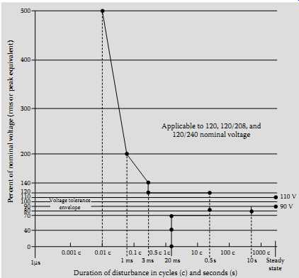
FIG. 25 ITIC susceptibility profile (curve) for sensitive equipment (electronic
equipment). (Fluke Corporation)
Peak voltage and real-time stamps are provided.
TVS suppressors (TVSS): Fortunately, transient protection is not expensive.
Virtually all electronic equipment has (or should have) some level of protection built in. One commonly used protective component is the MOV which clips the excess voltage. TVSS are applied to provide additional transient protection. TVSS are low voltage (600 V) devices and are tested and certified to UL 1449. UL 1449 rates TVSS devices by grade, class, and mode. As an example, the highest rating for a TVSS would be grade A (6000 V, 3000 A), class 1 (let-through voltage of 330 V max), and mode 1 (L-N suppression). The proper rating should be chosen based on the load's protection needs:
A lower grade might result in a TVSS that lasts 1 year instead of 10 years. The solid-state components in a TVSS will themselves deteriorate as they keep on taking hits from transients.
A lower class might permit too much let-through voltage that could damage the load. Class 1 is recommended for SMPS.
A mode 2 device would pass transients to ground, where they could disrupt electronic circuit operation.
Voltage susceptibility profile: The new Information Technology Industry Council (ITIC) profile ( FIG. 25) is based on extensive research and updates of the Computer Business Equipment Manufacturers Association (CBEMA) curve. The CBEMA curve now the ITIC curve was the original voltage susceptibility profile for manufacturers of computers and other sensitive equipment. Similar curves are being developed for 230 V/50 Hz equipment and for ASDs. Sensitive equipment should be able to survive events inside the curve. Events outside of the curve could require additional power conditioning equipment or other remedial action. A major change in ITIC is that the ride-through times for outages as well as the tolerance for sags have both been increased. The field troubleshooter must keep in mind that the profiles are recommendations and that a particular piece of equipment may or may not match the profile. The profiles are useful because, when recorded events are plotted against them, they give a general idea of the voltage quality at a particular site.
6.3.8 Lightning
Lightning protection plays a vital part in the overall PQ of an installation.
Lightning occurrence varies by geography, with Florida being the lightning capital of the United States. Lightning does not have to score a direct hit to be disruptive. It has so much energy that it couples surges into conductors, both those exposed to air and those buried in the ground. Basic lightning protection has two main requirements:
Effective grounding: A low impedance of the grounding electrode system to earth is important. But, equally important is that all parts of the grounding system be bonded together: all ground electrodes are bonded (and extraneous ground rods removed), structural steel is tied to service entrance ground, all grounding connections are tight and free of corrosion, etc. This minimizes the phenomenon called transferred earth potential, where large surge currents create large voltage differences between two ground points with different impedances to earth. This same grounding practice is important for performance reasons, as it tends to minimize ground loop currents that circulate in an attempt to equalize ground potentials.
Surge arrestors: A surge arrestor "is a protective device for limiting surge voltages by discharging or bypassing surge current…," per NEC Article 280. Since the surge current is bypassed to ground, surge arrestors are only as effective as the grounding system. Surge arrestors are sized for the location where they are installed. Three categories are defined (ANSI/IEEE C62.41-2002).
======
TBL. 16
Inspection of Lightning Protection System
Check ---Look for ---- Reason
Surge arrestors, Installed at main service panel, subpanels, and critical equipment Lightning is high energy and needs multilevel protection To minimize high frequency impedance, leads should be short, with no bends Lightning has high frequency components. Shorter leads have less XL and less impedance at high frequency Grounding electrode conductors at service entrance or at SDS, Grounding electrode connections are not loose or corroded Ensure low impedance ground to minimize potential to ground with lightning induced surges, Grounding conductor should not be coiled or have unnecessary bends, Minimize impedance to high-frequency components of lightning Grounding electrode bonding All grounding electrodes should be effectively bonded together (<0.1 W) Prevent difference in earth potential between electrodes in event of lightning Separately driven (isolated) electrode
Electrode and equipment ground should both be tied to building steel, and thereby to the service entrance ground Same as above-entire grounding system should be an equipotential ground plane for lightning
Datacom cabling that runs between buildings
Surge arrestors on datacom cabling or use of fiber optic cables
Datacom cabling run between buildings can be a path for surge currents, due to differences between building earth potentials
======
A surge arrestor at an outside installation is closest to the lightning event and must absorb most of the energy. This is considered a Category C location (corresponding to CAT IV in IEC 61010). Category B refers to feeders and distribution panels (equivalent to CAT III in IEC 61010), and Category A refers to receptacle connected surge arrestors (equivalent to CAT II).
Surge arrestor or TVSS: A surge arrestor is there to protect the insulation and, ultimately, prevent failures that could lead to fires. It’s not necessarily designed to protect sensitive equipment. That's the job of the TVSS. Refer to an inspection guide on Inspection of Lightning Protection System which is given in TBL. 16.
6.3.9 Polyphase Induction Motors
About two-thirds of the electric power in the United States is consumed by motors, with industrial three-phase motors above 5 hp (7 kW) being by far the bulk of that load. They are linear loads and therefore don’t contribute to harmonics. They are, however, the major contributor to reduced DPF, which is a measurement of the effective use of system capacity.
Measurements
Voltage unbalance: Voltage unbalance should not exceed 1%-2% (unless the motor is lightly loaded). The reason for such a small tolerance for voltage unbalance is because it has a very large effect on current unbalance, in the neighborhood of 8:1. In other words, a voltage unbalance of 1% can cause current unbalance of 8%. Current unbalance will cause the motor to draw more current than it otherwise would. Also, the unbalance voltage being delivered to motor terminals will cause the flow of negative sequence cur rents. Negative sequence currents produce opposing torque which the motor has to overcome therefore it will draw more current, thereby overheating the motor. For example a 3% voltage unbalance raises the motor winding temperature by 25% (refer to Section 10.10 in Section 10). The net effect of voltage unbalance is more heat and heat is the enemy of motor life, since it deteriorates the winding insulation.
Voltage unbalance can be caused by severe load unbalance but it could just as easily be caused by loose connections and worn contacts. Example of volt age unbalance calculation can be made as follows:
Example:
Max deviation from average
% = 100 unbalance Average(of three phases)
Voltage %THD and harmonic spectrum: Voltage THD should not exceed 5% on any phase. If the voltage distortion on any phase is excessive, it can cause current unbalance. The usual culprit is the fifth harmonic and therefore the harmonic spectrum should be examined for the fifth in particular. The fifth is a negative sequence harmonic which creates counter-torque in the motor.
A motor fed by a voltage with high fifth harmonic content will tend to draw more current than otherwise. This is a major problem when across-the-line or soft-start motors share the same bus with VFDs.
Current unbalance: To find current unbalance, measure amps in all three phases. Do the same calculation as for voltage unbalance. In general, current unbalance should not exceed 10%. However, unbalance can usually be tolerated if the high leg reading does not exceed the nameplate full load amps ( FLA) and service factor (SF). The FLA and SF are available on the motor nameplate. If the voltage unbalance and the voltage THD are within limits, high current unbalance can be an indication of motor problems, such as damaged winding insulation or uneven air gaps. Current measurement will also find single-phasing. If a three-phase motor loses a phase (perhaps caused by a blown fuse or loose connection), it may still try to run single phase off the remaining two phases. Since the motor acts like a constant power device, it will simply draw additional current in an attempt to pro vide sufficient torque. A voltage measurement alone won’t necessarily find this condition, since voltage is induced by the two powered windings into the non-powered winding.
Loading: Measure current draw of the motor. If the motor is at or near its FLA rating (times the SF multiplier), it will be more sensitive to the additional heating from harmonics, as well as current unbalance. A motor that is only lightly loaded is usually safe from overheating. On the other hand, its efficiency and DPF are both less than optimal. Most motors reach maximum efficiency at 60%-80% of full load rating. DPF is maximum at rated load (including SF) and drops off, especially at less than 80% of rated load. This leads to the conclusion that, to the degree a motor load is constant and predictable, 80% of rated load is the most efficient operating range.
Inrush (lock rotor current): Motors which are started across-the-line (as opposed to those using soft-starts or drives) draw a current inrush, also called locked rotor current. This inrush tapers off to normal running current as the motor comes up to speed.
Older motors draw an inrush of typically 500%-600% of the running current. Newer energy efficient designs draw brief inrushes as high as 1200% of running current, a direct result of the lower impedances which help make them more energy efficient in the first place.
High torque, high horse power motor loads require proportionally higher inrush.
Motor loads started at the same time will have a cumulative inrush.
• Another source of inrush is UPS and VFD systems with diode converters. They draw inrush current as their capacitor banks first charge.
Effects of inrush current:
1. Inrush causes voltage sags if the source voltage is not stiff enough.
Therefore, relays and contactor coils might drop out (typically, the sag would have to get as bad as about 70% of normal line voltage); or, if they hold in, their contacts might chatter (especially if the additional load causes a long-term undervoltage). Control circuits might reset or lockup (at 90% and below). Drives might trip off-line (undervoltage trip).
2. High peak demand periods, which may cause higher utility bills.
3. Cycling loads can cause periodic sags, which might show up as flickering lights.
4. If the motor is required to start up a high torque load, the inrush can be relatively prolonged (e.g., 10 to 20 s or more) and this can cause nuisance tripping as the overload heaters trip the motor starter.
PF: If the PF of the motor is low, it can be improved by applying capacitors to supply the required reactive volt-amperes (kVAR). To size PF correction capacitors, it’s necessary to measure the DPF and active power consumption (kW) of the motor load. These measurements assume that the motor voltage and current are balanced. Therefore, before undertaking PF correction, first make sure that voltage and current unbalance are within limits.
Either problem can shorten motor life and should take priority over DPF correction.
6.3.10 PQ Measurements of VFDs
AC VFDs can be both a source and a victim of poor PQ. VFDs are also referred to as ASDs. Although ASDs are usually depicted as the culprit in the PQ scenario, there are ways in which they can be a victim load as well. ASDs can be affected as follows.
Capacitor switching transients: High-energy (relatively low frequency) transients that are characteristic of utility capacitor switching can pass through the service transformer, feeders, and converter front-end of the drive directly to the DC link bus, where it will often cause a DC link overvoltage trip. Input diodes could also be blown out by these transients.
Voltage distortion: If high-voltage distortion shows up as excessive flat-topping, it will prevent DC link capacitors from charging fully and will diminish the ride-through capability of the drive. Thus a voltage sag which would not normally affect a drive will cause the drive to trip on undervoltage.
Grounding: Improper grounding will affect the internal control circuits of the drive, with unpredictable results.
ASDs as culprit loads: A drive can definitely be a culprit load and have a major impact on system PQ. But before discussing the problems, let us put in perspective the positive effects of drives on PQ. First of all, they offer built-in soft-start capabilities. This means there will be no inrush current and no voltage sag effect on the rest of the system. Second, if the drive is of the PWM type, with a diode converter front-end, the DPF is high (commonly >95% at rated load) and more or less constant throughout the range.
This means that drives can reduce energy usage and correct for DPF at the same time. It’s a good thing too, because drives and PF correction capacitors don’t mix. Capacitors are vulnerable to the higher frequency harmonic currents generated by drives, since their impedance decreases as frequency increases. The type of drive has a major impact on the PQ symptoms, because of the different converter designs (converters or rectifiers turn AC to DC and are the first stage of the drive). There are two major types of converter design.
1. SCR converter with VSI/variable voltage inverter (VVI) drives Commonly called six-step drives, they use SCRs in their converter front-ends (the following discussion also applies to CSI drives, which also use SCRs). VSI ( FIG. 26) and CSI drive designs tended to be applied on larger drives (>100 hp). SCR converters control the DC link voltage by switching on (or gating) current flow for a portion of the applied sine wave and switching off at the zero-crossing points. Unlike diodes, SCRs require control circuits for gate firing.
For the SCR converter, there are three main issues that affect line-side PQ:
Commutation notches. SCR switching or commutation is such that there are brief moments when two phases will both be "ON." This causes what is in effect a momentary short circuit that tends to collapse the line voltage. This shows up as notches on the voltage waveform. These notches cause both high V-THD and transients.
The solution is to place a reactor coil or isolation transformer in series with the drive's front end to clean up both problems.
DPF declines as drive speed decreases. This is not as serious a problem as it sounds, because the power requirement of the drive-motor load decreases even more.
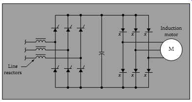
FIG. 26 Electrical circuit of a VSI drive. (Fluke Corporation)
Harmonic currents, typically the fifth and seventh, are generated by VSI drives.
2. Diode converter with PWM drives
The other and more common converter design uses diodes and is used in the PWM drive ( FIG. 27). The diodes require no switching control circuitry.
One of the main trends in the industry has been the proliferation of PWM drives, mainly due to the continued development of fast switching, efficient insulated gate bipolar transistors (IGBTs) used in the inverter section of the drive (inverters turn DC to AC). For all practical purposes, PWM drives are the industry standard. For the diode converter, the main PQ issue is harmonics. The actual harmonic orders being generated depend on the number of diodes in the front end. For three-phase conversion, a minimum set of six diodes is required. This six-pulse converter will generate fifth and seventh harmonics. If a 12-pulse converter were used, the 11th and 13th harmonics will be generated instead of the fifth and sixth-and, very importantly, for the same load, the amplitude of the 11th and 13th would be considerably less than the 5th and 6th. Therefore, the THD would be less. The vast majority of drives, however, are six-pulse PWM style, which is one reason we see so much fifth harmonic on the system.
Harmonics solutions: There are a number of solutions to mitigating drive-generated harmonics. They are the following:
1. Harmonic trap filters ( FIG. 28) These are typically LC networks connected in parallel at the source of the harmonics (in other words, at the drive input). They are tuned to just below the fifth harmonic (typically 280 Hz) and will tend to sink both fifth and much of the seventh harmonic. Obviously, they must be sized to the harmonic generating load.
2. Phase-shift transformers
This can be as simple as a delta-wye transformer feeding one drive(s) and a delta-delta feeding another drive(s). There is a 30° phase-shift effect between these two configurations, which effectively results in cancellation of harmonics at the closest upstream PCC. The cancellation effect is optimal when both loads are more or less equal.
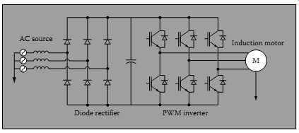 FIG. 27 Electrical circuit of the PWM drive. (Fluke Corporation)
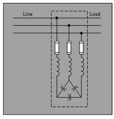
FIG. 28 Harmonic trap filter. (Fluke Corporation)
6.3.11 Power System Resonance
Is it possible to install PF correction capacitors and have PF get worse? It certainly is and a starting place to understanding this puzzle lies in the distinction between DPF and total PF. The penalty for not understanding the difference can be blown capacitors and wasted investment. Total PF and DPF are the same in one basic sense: they are the ratio of real power to apparent power, or watts to VA. DPF is the classic concept of PF. It can be considered as the PF at the fundamental frequency. Total PF now includes the effects of fundamental and of harmonic currents (it is also referred to as true PF or DPF) (see FIG. 13). It follows that with the presence of harmonics, PF is always lower than DPF and is also a more accurate description of total system efficiency than DPF alone. Strictly speaking, the term PF refers to total PF, but in practice can also be used to refer to DPF. Needless to say, this introduces some confusion into discussions of PF. You have to be clear which one you are talking about.
DPF: Lower DPF is caused by motor loads which introduce the need for reactive power (VARs). The system has to have the capacity, measured in VA to supply both VARs and watts. The more VARs needed, the larger the VA requirement and the smaller the DPF. The cost of VARs is accounted for in a PF penalty charge.
Utilities often levy additional charges for DPF below a certain level; the actual DPF number varies, but typical numbers are 0.85 to 0.9. To reduce VARs caused by motor loads, PF correction capacitors are installed. Upstream system capacity, both in the plant and at the utility level, is released and avail able for other uses ( FIG. 29). Historically, this has been the gist of the PF story: a relatively well-known problem with a relatively straightforward solution.
Harmonics and capacitors: Harmonics have had a dramatic impact on the application of PF correction. The motor and capacitor loads described above are all linear and for all practical purposes generate no harmonics. Nonlinear loads such as VFDs, on the other hand, do generate harmonic currents. Take a plant which is step-by-step putting VFDs on its motor loads.
VFDs generate significant harmonic currents (fifth and seventh on six-pulse converter drives). Suddenly the fuses on existing PF correction caps start blowing. Since these are three-phase caps, only one of the three fuses might blow. Now you have got unbalanced currents, possibly unbalanced volt ages. The electrician replaces the fuses. They blow again. He puts in larger fuses. Now the fuses survive, but the capacitor blows. He replaces the capacitor. Same thing happens. What is going on? Harmonics are higher frequency currents and higher the frequency, the lower the impedance of a cap. The cap acts like a sink for harmonic currents.
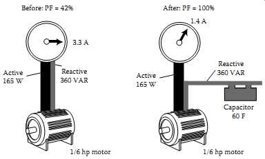
FIG. 29 Capacitor corrects DPF. (Fluke Corporation)
[Before: PF = 42% 3.3 A Active 165 W Reactive 360 VAR 1/6 hp motor After: PF = 100% 1.4 A Active 165 W Reactive 360 VAR Capacitor 60 F 1/6 hp motor]
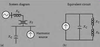
Power system resonance: In a worst-case scenario, the inductive reactance (XL) of the transformer and the capacitive reactance (XC) of the PF correction cap form a parallel resonant circuit: XL = XC at a resonant frequency which is the same as or close to a harmonic frequency. The harmonic cur rent generated by the load excites the circuit into oscillation. Currents that are many times greater than the exciting current then circulate within this circuit. This so-called tank circuit can severely damage equipment, and it will also cause a drop in PF. This resonant condition often appears only when the system is lightly loaded, because the damping effect of resistive loads is removed. In other words, we have what the audio buffs call a high Q circuit. ( FIG. 30).
Start with harmonics mitigation: The correct solution path starts with measuring and mitigating the harmonics generated by the drives. Harmonic trap filters would generally be called for. These trap filters are installed locally on the line side of the drive. Their effect is very much like the traditional PF correction cap, in two senses: they reduce DPF as well as PF, and also they localize the circulation of the problem harmonics (generally the fifth). Harmonics mitigation and traditional DPF correction should be addressed as one systems issue. In other words, manage total PF, not just DPF.
6.3.12 Commercial Lighting Load
Lighting loads are a major load for many large facilities. Evaluating these circuits is important for both energy conservation and PQ (see TBL. 17). Keep in mind that commercial lighting loads are wired single phase, with the loads connected from phase-to-neutral. Typically, the phase-to-phase voltage is 480 V, with the phase-to-neutral voltage at 277 V. Measurements must be taken at the lighting panel, one phase at a time, since power consumption and PF could vary on each phase. Consider the following factors from the PQ perspective.
===
TBL. 17
Measurements on Commercial Lighting Loads Measurement Look for Instrument
1. Power consumption (kW) Balance among three phases Three-phase/ single-phase analyzer
2. DPF and PF Magnetic ballast will have low DPF Electronic ballast may have low total PF, although new generations of ballast often have harmonic mitigation built-in Same
3. %THD Current %THD <20% is desirable Same
4. Voltage stability Unstable voltage can cause lights to flicker Same
====
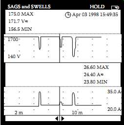
FIG. 31 Fluke 43 trends voltage (top) and current (bottom) simultaneously.
Current swells/inrush caused voltage sags, indicating that a load downstream
from the measurement point is the cause of the disturbance. (Fluke Corporation)
Power consumption: Excessive phase unbalance can cause voltage unbalance, which in turn can affect three-phase motor loads.
PF: Ballast with low PF might have lower cost-of-purchase but higher cost of-operation.
THD: Current THD should be considered when selecting ballast, especially if there is a possibility of transformer overloading.
Voltage stability: The sags and swells mode of the Fluke 43 (or similar instrument) is especially useful for recording repetitive voltage sags which can show up as flickering lights. Both current and voltage are monitored simultaneously ( FIG. 31). This helps us to tell if sags are downstream of the measuring point (load related) or upstream (source related). For example, if voltage sags while current swells, a downstream current inrush likely caused the sag. If both voltage and current sag at the same time then some event upstream has caused the sags. It could be an upstream load like a motor on a parallel branch circuit which drew down the feeder voltage. Or it could be source voltage related, for example, a lightning strike or breaker trip/re-closure on the utility distribution system.
6.3.13 Summary of PQ Problems
The following summary is provided of the PQ problems discussed in this section beginning from utility source all the way down to 120 receptacles.
These PQ problems are:
Lightning: Can be extremely destructive if proper surge protection is not installed. It also causes sags and undervoltages on the utility line if far away. If close by, it causes swells and overvoltages. But in the final analysis, lightning is an act of nature and not in the same category as the damage man does to himself.
Utility automatic breaker re-closure: Causes short duration sags/outages, but better than the alternative, a longer-term outage.
Utility capacitor switching: Causes a high-energy voltage disturbance (looks like an oscillating transient riding on the wave). If the cap bank is near the facility, this transient can propagate all through the building.
Facility without enough distribution transformers: Trying to cut corners in the wrong places; running 208 V feeder up 20 stories is not the road to PQ.
Gen-sets not sized for harmonic loads: Excessive voltage distortion affects electronic control circuits. If SCR converter loads are present, notching can affect frequency control circuits.
PF correction capacitors and the effects of harmonics: Harmonics and caps don’t mix. Those bulging capacitors are crying for help.
Inrush currents from high torque motor: Causes voltage sags if the load is too large or the source impedance too great. Staggered motor starts can help.
Undersized neutrals at panelboard: In the era of the third harmonic currents, neutrals can easily carry as much current or more current than the phase conductors. Keeping undersized neutral leads to overheated neutral and lugs, potential fire hazards, and high N-G voltage.
Running power and signal cables together: Think of the signal cable as a single-wire transformer secondary and the power cable as the primary. The opportunities for coupling are endless.
Loose conduit connections and lack of green wire grounding conductor: Causes open or high impedance ground circuit. Not good for PQ or safety.
Hi-frequency noise: The most effective high frequency grounding technique is the installation of a SRG.
IG rods ( FIG. 32): They are a safety hazard because the earth is a high impedance path and will prevent enough current from flowing to trip the breaker. They also cause ground loops; after all, every electron still has to go back where it came from. Further, if a person comes in contact with the ground where the step potential is high because of the high impedance path of the earth, the person will get shocked, injured or killed. One of the great mysteries of PQ is how some manufacturers get away with insisting that their equipment warranty is void unless an IG rod is installed.
This installation is in violation of the NEC requirements for single point grounding.
Shared neutrals on branch circuits: Causes load interaction and overloaded neutrals.
Laser printers and copiers sharing branch circuits with sensitive loads: Guaranteed periodic voltage sags and switching transients.
Mis-wired receptacles (N-G swapped): Hard to believe, but they are very common in most facilities. Guaranteed to put return currents on the ground conductor and create a noisy ground.
Data cables connected to different ground references at each end: Shows up as voltage between equipment case and the data cable connector.
Illegal N-G bonds: Guaranteed to put return currents on ground. Not only is it a PQ problem, it’s a plumbing problem. Circulating ground currents cause corrosion of water pipes.
===
Load current Neutral return current error Separately derived system Line Neutral N-G bond Ground Line Neutral Ground Isolated ground, ground rod, cold water pipe, etc.
Earth ground Panel
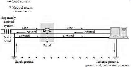
FIG. 32 IG rod can cause ground loops. Common problem
with machine tool installations. (Fluke Corporation)
===