AMAZON multi-meters discounts AMAZON oscilloscope discounts
A permanent-magnet stepping motor with bipolar windings is illustrated in FIG. 5. With this winding configuration on the stator, the driver must be able to send current in either direction through a selected pair of windings so that the resultant magnetic field experienced by the rotor can be either N-S or S-N in direction. This calls for push-pull or H-bridge drivers. Other things being equal, stepping motors with bipolar windings tend to exhibit more precise operating characteristics than do stepping motors with unipolar windings. This is because the polarity reversals experienced by the bipolar windings are effective in quickly neutralizing the stored energy in the windings. By contrast, the unipolar type of motor tends to have a “mushy” running characteristic. However, it’s also true on an “other things being equal basis,” that the unipolar winding format allows higher torque at higher stepping rates. It’s fitting to state that an earlier objection to the bipolar type of motor has been largely over come. This pertains to the requirement for more complex drive electronics. This need is now easily met by control ICs.
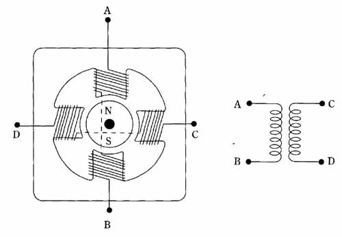 FIG. 5 Permanent-magnet stepping motor with bipolar windings. The drive
circuit can send current through the windings in either direction so
that the stator poles can be either N or S. Complementary symmetry, push-pull,
or H-bridge drivers can be used.
FIG. 5 Permanent-magnet stepping motor with bipolar windings. The drive
circuit can send current through the windings in either direction so
that the stator poles can be either N or S. Complementary symmetry, push-pull,
or H-bridge drivers can be used.
Three commonly used driving formats are used for bipolar stepping motors. These are shown in the diagram of Figs. 6, 7, and 8. In the “one-phase-on” method of FIG. 6, full-step rotational increments are obtained. Because only one phase of the stator windings is energized at a time, a penalty in torque must be acceptable when this drive sequence is used.
In the two-phase-on drive method shown in FIG. 7, full-step increments of rotor rotation are also obtained, but the rotor now lines up at the inter-phase positions. Higher torque is available than from the previous method because now two phases contribute to the stepping process.
As might be expected, the two described phase sequence can be combined to produce the half-step drive technique shown in FIG. 8. This is brought about by alternating between the full-step drive methods as the stepping process sequences. Naturally, there are now eight, rather than four, unique states per revolution.
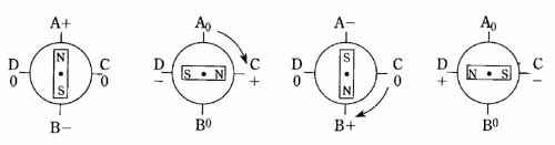
FIG. 6 The one-phase-on method of driving a permanent-magnet stepping
motor. Note that only one phase at a time is energized. The rotor turns
in full-stop increments in order to line up with the magnetic field of
the stator windings.
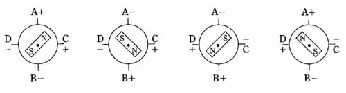
FIG. 7 The two-phase-on method of driving a permanent-magnet stepping
motor. This phase sequence produces higher torque than the one-phase-on
method. The rotor, however, still turns in one-step increments. Note
that the two phases are always both energized to produce rotation.
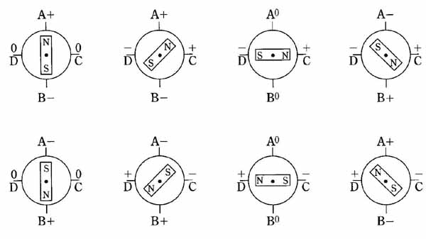
FIG. 8 The half-step method of driving a permanent-magnet stepping
motor. Here, the one-phase-on and the two-phase-on driving methods are
combined. The phase sequence, or “firing order”, alternates between the
two methods. The net result is that the rotor turns in half-step increments.
In order to gain finer resolution and smoother torque, real-life stepping motors might have multiple rotor poles, rather than the two depicted in the diagram. An even number of permanent-magnet poles are always used. This statement might appear self-evident, but there is another type of stepping motor in which the actual number of rotor poles is not what might be expected from a “common sense” approach.
An example of stepping-motor system utilizing bipolar windings is shown in FIG. 9. The same stepping motor can be used as in the unipolar circuit of FIG. 4, but the winding center taps are then left unconnected. As in FIG. 4, two shift-register ICs provided the stepping logic for either half-, or full-step operation. In this circuit, current limiting for the stator windings is provided by the two 9- resistances. Two of each component and device depicted in the driver portions of the circuit of FIG. 9 are needed because this circuit is drawn for only one stator winding. However, the logic suffices, as shown , for both motor windings. Specifically, the requirement in FIG. 9 is for four N-channel power MOSFETs, four P-channel power MOS FETs, but only two MC14194 ICs.
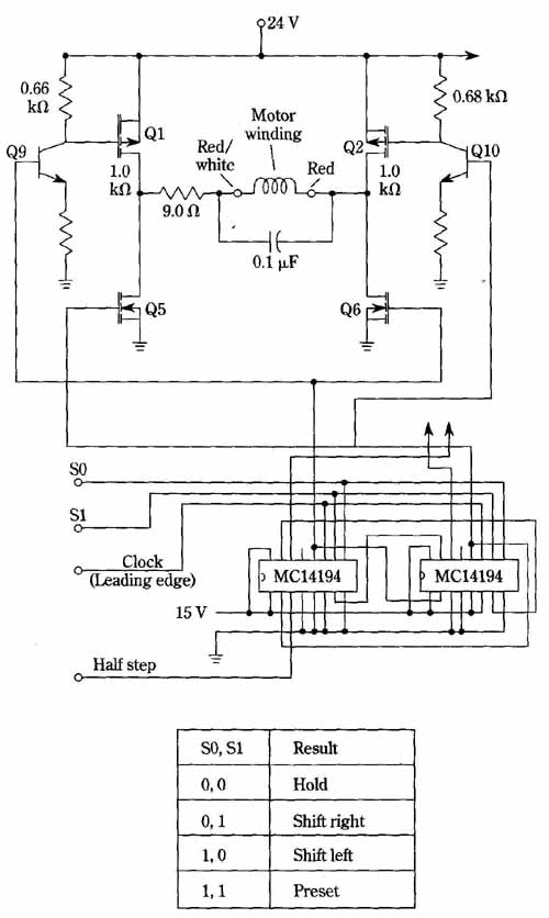
FIG. 9 Example of stepping motor drive with non-center-tapped windings.
This is a bipolar system. The complete logic for a two-phase motor is
shown. Only the push-pull complementary-symmetry drive for one phase
is shown for simplicity; identical drive circuitry is used for the two
phases. Motorola Semiconductor Products, Inc.
The parameters of a full winding of the stepping motor used in the previous examples are as follows: the resistance is 2.5 ohm inductance is 31.8 uH and rated cur rent is 2.0 A. The designer of these motors must trade off the conflicting needs imposed by torque, magnetic saturation, temperature rise, and winding space; he or she then hopes the inductance will be as low as possible so that the torque will hold up for reasonably high stepping rates. In practice, circuit and operating techniques might have to be resorted to overcome the current-retarding effect of winding inductance. The bottom line is that a high stepping rate requires a high d in the mo tor windings. The user of the motor can increase the d by raising the dc supply voltage and then relying either on series resistance, or on a switching technique, to keep the average winding currents at rated levels.
What appears to be a resonating capacitor across the motor winding is not large enough to function in that manner within frequency bands involved in the operation. In deed, both electrical and mechanical resonances tend to be very undesirable. This capacitor absorbs inductive-kickback energy, thereby protecting the power MOSFETs from avalanching. This protective function is supposed to be the entire job of the internal body diodes of the MOSFETs, but in practice they don’t turn on instantaneously; it requires about 300 nanoseconds for these diodes to become fully conductive.
Some semiconductor firms market power ICs comprised of four power MOS FETs designed to function as drivers of bipolar stepping motors. This keeps the parts count down and economizes on production costs.
