AMAZON multi-meters discounts AMAZON oscilloscope discounts
.The possibility of controlling dc motors with the use of regulated power supplies was discussed in a previous section. There, it was mentioned that either a series-pass (linear) or switching-type regulator could be used. Moreover, it’s quite easy to build a high-performance switching supply by using the pulse-width modulator ICs now avail able. Thus, unlike the situation prevailing in past years, the high-efficiency inherent in the switching technique can be readily realized without acquiring a manufactured supply. Only a few components need be associated with such a dedicated IC in order to obtain satisfactory results. Gone are most of the difficulties with instability, erratic performance, and catastrophic destruction of semiconductor devices that usually at tended the breadboarding of switching supplies via the discrete-device approach.
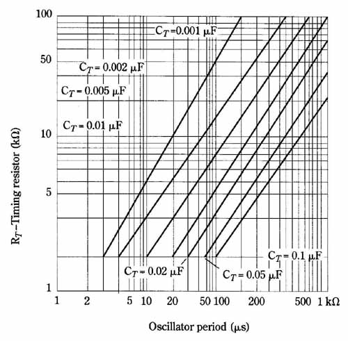
FIG. 25 Oscillator period of the LM3524 as a function of the external
capacitor resistor. This graphical technique provides a family of nearly
straight lines. Oscillator frequency is the reciprocal of the period.
National Semiconductor Corp.
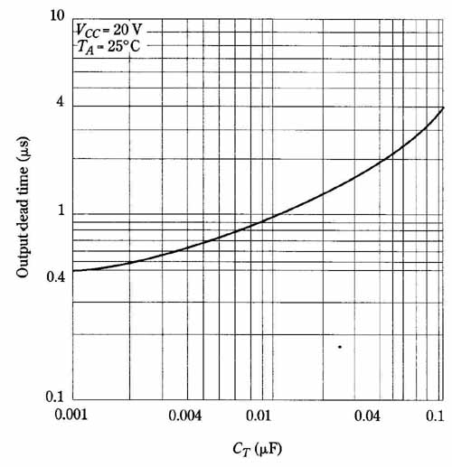
FIG. 26 Deadtime developed by the LM3524 as a function of the external
timing capacitor. For a given switching rate, deadtime is greater with
larger capacitors and smaller timing resistors. National Semiconductor
Corp.
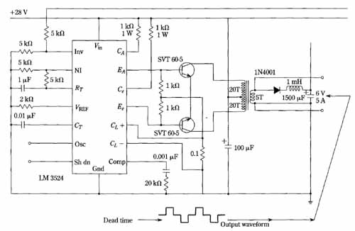
FIG. 27 Push-pull inverter using the LM3524 regulating pulse width
modulator. Deadtime in waveform pre vents destructive simultaneous conduction
in the push-pull output transistors.
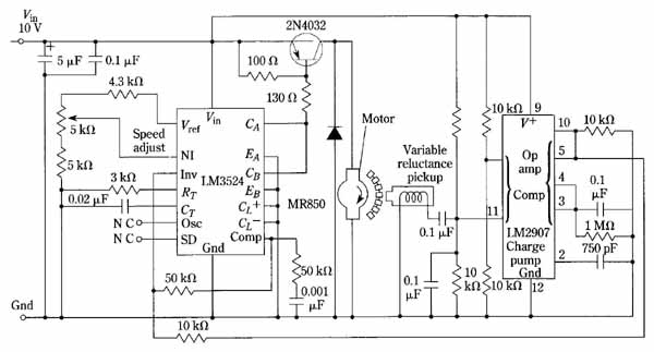
FIG. 28 is an example of the use of the switching-regulator approach
to dc motor control. Notice that the switching regulator proper is comprised
of the LM3524 pulse- width regulating IC, the switching transistor, and
a handful of passive components.
The circuitry to the right of the motor provides the function of an electronic tachometer. This is only one of several techniques that can be used to obtain the dc error signal to apply to the LM3524. A small dc generator of the permanent-magnet type could be mechanically coupled to the motor. An ac tachometer, together with a rectifier and filter, could also be employed. In such an application, too great a time constant on the part of the filter could produce sluggish response, as well as overall loop instability. And optical methods with encoder disks could be used in a some what analogous way to the rotating-magnet scheme shown.
The LM2907 is also a dedicated IC, providing in this case, the function of frequency to dc converter. This neatly circumvents the problems of sluggish response and possible instability.
The interesting aspect of such control systems as this one is that the “textbook” characteristics of the motor no longer apply. Rather, the speed, torque, and start-up behavior are very much governed by the electronic control logic. In some instances , for example, quite similar performance can be forthcoming from either a series, or a shunt motor! Without the electronic control, such motors would, of course, exhibit widely different characteristics.
FIG. 28 Use of the LM3524 pulse-width modulator IC to control a dc series
motor. The circuitry to the right of the motor is, in essence, an electronic
tachometer, which feeds a dc error signal to the LM3524.
