AMAZON multi-meters discounts AMAZON oscilloscope discounts
.The LM3524 regulating pulse-width modulator IC is typical of similar units made by several semiconductor firms. FIG. 23 shows the block diagram of the internal circuitry of the LM3524. Pulse-width modulation is accomplished by applying a sawtooth wave and a dc voltage to the inputs of a comparator op amp. The level of the dc voltage varies with that of the error signal—a sampled portion of the regulated output voltage. In response to this variation, the pulses appearing at the output of the comparator are duration modulated. Multiple-input NOR gates then drive a pair of output transistors. These transistors have free emitter and collector terminals and can be used for a wide variety of push-pull, bridge, and single-ended inverters and switching stages.
Unfortunately, there has been a lack of standardization in these pulse-width modulator ICs. FIG. 24 shows the dual-in-line packages of two manufacturers. While basically similar in ultimate function, these ICs are actually not identical. Yet, both of them could provide very similar electrical performance when appropriately connected in many applications.
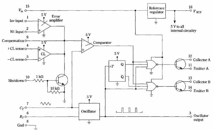
FIG. 23 Block diagram of the LM3524 regulating pulse-width modulator.
The undedicated output-transistors provide optional drive for single-ended,
push-pull, bridge, or dc series-pass transistors. National Semiconductors
Corp.
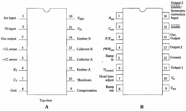
FIG. 24 Pin connections of similar pulse-width modulators made by two
manufacturers. Example of non- standardization. The two ICs provide nearly
the same functions. (A) National Semiconductors LM3524. (B) Motorola
MC3420.
In the National LM3524, as well as in other firm’s products, the switching frequency is determined by an external capacitor and resistor. For the LM3524, FIG. 25 shows the oscillator period as a function of different combinations of the external capacitor and resistor. By plotting the chart in this manner, a family of nearly straight lines result. Frequency is the reciprocal of period. However the frequency developed by a driven push-pull inverter will be half the oscillator frequency.
Of importance in some inverter situations, the dead time is greater at a given frequency if a large capacitor and small resistor are used to set the oscillator time constant. This is shown in FIG. 26. The principal use of dead time is to prevent simultaneous conduction in the push-pull or bridge transistors of a driven inverter. Much more than the needed dead time can degrade efficiency and interfere with regulation, however.
A typical inverter using the LM3524 is shown in FIG. 27. Circuits of this kind are very useful for providing selected speed options for induction and synchronous motors. Minimal filtering can be implemented, when satisfactory motor performance is not obtained from the output waveform.
