AMAZON multi-meters discounts AMAZON oscilloscope discounts
Although motors tend to operate quite well with square waves, another nonsinusoidal waveform can be produced that will more closely approach the efficiency and temperature rise that motors are rated for when driven by sine-wave power. Other improvements that can be brought about with this waveform are decreased noise and smoother torque. The -waveform referred to is the stepped wave illustrated in FIG. 29. Interestingly, this quasi-square wave has the same peak and RMS values as the enclosed sine-wave depicted in dashed lines. Because of this, we find statements in the technical literature that say a motor driven by such a stepped wave essentially “sees” a sine wave. This is not quite true, but in practice it’s found to be very nearly so, especially because the inductance of the motor exerts filtering action on the high-frequency harmonics of the wave.
Note, however, that what has been stated applies only to the special stepped wave in which the horizontal sections are 90 electrical degrees in duration. This structure is evident in FIG. 29; if this one-cycle wave were continued for many cycles, the 90° durations would be clearly visible.

FIG. 29 Unique stepped wave with peak and rms values identical to a
sine wave. A motor impressed with such a waveform should behave very
much as with the enclosed sine wave.
The schematic diagram of an inverter for producing the described stepped waveform from a 12-volt dc source is shown in FIG. 30. Although the power output is in the 40—50 watt region, circuit modification for higher power levels is relatively easy. Larger power MOSFETS are available, and paralleling is easy with these devices. A replacement output transformer for Ti would also be required. However, larger power MOSFETS would be just as easy to drive as the prescribed ones. The salient feature of this circuit is the “brainy” portion that creates the desired stepped wave form. This comprises , for the most part, IC2, the decade counter, IC the quad op amp, and Q7, used as a polarity inverter.
As shown, the stepped-wave inverter outputs a frequency of 75 Hz. This frequency was selected in order to provide a safety margin against core saturation of output-transformer T1. However, 60-Hz operation can be obtained by increasing the value of either R27 or C1. To a first approximation the factor of increase for either of these timing-circuit components will be 1.25. Probably a little experimentation will be needed because other factors bear a secondary effect on the oscillation frequency of IC 1-a. Protection against magnetic saturation of T1 can be realized by using a larger transformer than would be dictated by only its current-carrying capacity.
The waveform diagram of FIG. 31 shows how the pulses from decade- counter 1C2 are combined to produce the desired stepped waveform at the output of the inverter. The parts list is depicted in Table 3. This is an excellent project for the experimenter.
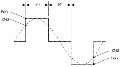 FIG. 30 Schematic diagram of step-wave inverter. High efficiency is
attained, and the output waveform is better for operating motors than
a square wave. Greater power can be realized by paralleling more power-MOSFETS,
or by using larger ones.
FIG. 30 Schematic diagram of step-wave inverter. High efficiency is
attained, and the output waveform is better for operating motors than
a square wave. Greater power can be realized by paralleling more power-MOSFETS,
or by using larger ones.
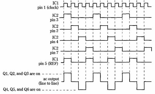
FIG. 31 Waveform diagram of step-wave inverter. Pulses from a decade
counter are sampled in such a way that divide-by-four triggering of the
output-stage occurs. The resultant stepped wave is made up of 90° segments,
and closely simulates a sine wave for motor operation.
-- --
Table 3. Parts list of step-wave inverter.
PARTS LIST
All resistors are 1/2-watt, 5% unless otherwise noted:
R1—R7—100 ohms
R8—1000 ohms
R9—1000 ohms, ½-watt
R10, R11—4700 ohms
R12—R16-—10,000 ohms
R17—10,000-ohm potentiometer
R18—R21—22,000 ohms, ½-watt
R22—R26-—100,000 ohms
R27—R28-—470,000 ohms
R29—1 megohm
Capacitors:
C1—0.001 uF, ceramic disc
C2—0.01 pF, ceramic disc
C3—0.0047 uF, ceramic disc
C4—0.05 uF 200 volts, ceramic disc or metal film
C5—C7—0.1 uF ceramic disc
C8—C9-—470 uF, 35 volts, electrolytic
Semiconductors:
IC1—LM324 quad op-amp
IC2—4017 CMOS decade counter
IC3—LM7805 or LM340-5 +5-volt regulator
D1—D7—1N4003 diode
Q1—Q6—IRF511 60-volt 3.5-amp MOSFET
Q7—2N2222 or 2N3904 NPN transistor
Other components:
T1—120/12.6 volt center-tapped 3-amp power transformer
J1—banana jack, red
J2—banana jack, black
J3—ac power receptacle
F1—3-amp slow-blow fuse
S1—SPST 6-amp switch
NE 1—neon indicator light with series resistor
Miscellaneous: fuse holder, perforated construction board, enclosure aluminum for heatsinks, standoffs for mounting circuit board, wire, solder, etc
-- --
Substitute IFRZ30 power-MOSFETS for higher output power (up to 250 watts). Use adequate heatsinks. Also substitute a Jefferson #216-1121 "buck-boost" transformer for T1. Connect 120-volt windings in parallel; connect 12-volt windings in series. Pay attention to phasing of these dual windings.
