AMAZON multi-meters discounts AMAZON oscilloscope discounts
.Manufacturers of regulated power supplies have been slow to adapt and specify their general product lines for motor-drive applications. Because of their apprehension of inductive loads and unpredictable current demands, substantial marketing opportunities surely have been lost. From the user’s vantage point, many application requirements could be conveniently satisfied with appropriate associations between dc motors and suitable power supplies. For example, a supply operating in the constant-current mode is likely to meet the needs of a motor drive application where inordinately high starting torque is not required and where the motor is subject to overloads and stalls. If operated from an ordinary unregulated supply, damage could occur to both the motor and the supply during such times. This is because a non-rotating dc motor generates no counter EMF and becomes , for practical purposes, a short circuit. Fuses and circuit breakers often turn out to be unsatisfactory or in convenient protection techniques.
FIG. 18 shows a motor-drive system for maintaining constant motor current under all operating conditions. The circuit is essentially a linear, series-pass regulator with bipolar output. By means of voltage programming at the input, the desired motor current can be selected. By reversing the polarity of this programming volt age, the direction of rotation can be reversed. The arrangement is best suited for use with a permanent-magnet motor. A shunt motor can be accommodated if arrangement is made for supplying its field current from a small auxiliary dc source. If a series motor is used, the direction-reversing feature will be sacrificed insofar as concerns voltage programming. Of course, reversal of rotation can still be had via appropriate switches to transpose the connections of either the series field or the armature. As shown, a 48-volt motor can be controlled with a maximum constant current of one ampere.
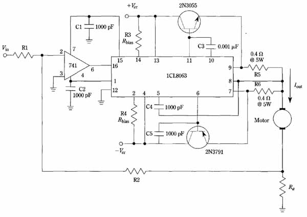
FIG. 18 Constant-current motor drive. The complementary-symmetry drive
IC provides current-regulated bipolar output for the motor. Selection
of R1, R2, and Ra is discussed in the text.
The dominant feature of the schematic diagram is the 1CL8063 integrated circuit module. This unique semiconductor device facilitates the drive of complementary symmetry power transistors from very ordinary op amps, such as the 741, as shown. By its use, the requirements of balanced output, protection against short circuits and against overdrive are automatically assured. Even though the input op amp operates from a ±12-volt supply, the output power transistors operating from a ±30-volt sup ply will be driven to full output. As previously mentioned, full output for this particular motor-control arrangement is one ampere. This one ampere output current will prevail even with the motor in a stalled condition. Another interesting aspect of the circuit is that the 741 op amp does not need an auxiliary power supply. This is be cause the LM 8063 module has an internal ±13-volt regulated supply (these voltages being available from pins 1 and 15).
The one ampere constant motor current can be realized by making Ra one ohm and R1 and R2 each 10 k-ohm. Then, ±1 volt for N to the op amp will produce ±1 ampere in the motor. The operational mode of this control technique is such that the motor current is governed by N However, once ‘ is selected, the motor current remains fixed regardless of motor speed, loading, or temperature.
