AMAZON multi-meters discounts AMAZON oscilloscope discounts
.The arrangement illustrated in FIG. 17 enables precise control of motor speed without resorting to feedback or servo techniques. On the one hand, the reference oscillator and the programmable divider provide precise frequencies for the two- phase synchronous motor. On the other hand, a synchronous motor operates only at the speed determined by its construction and the frequency of the applied voltage. Applying heavier mechanical loads does not slow such a motor until a critical loading is reached, whereupon it comes to a standstill. -
A two-phase motor requires voltages displaced by 900 for its two identical stator windings. This is commonly obtained, or approximated, with a capacitor connected in one winding. However, when different frequencies are impressed upon the motor, as in this application, it becomes necessary to switch in different capacitors to retain the quadrature phase relationship. To avoid such an inconvenience, a digital phase splitting method is used in this circuit. The two flip-flops form a two-bit ring that de livers quadrature-related square waves regardless of the frequency. At the same time, this ring performs an additional frequency division by a factor of four. This is easily taken into account in the programming of the frequency-divider proper.
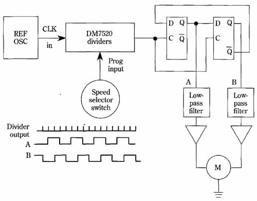
FIG. 17 Speed control of a synchronous motor with a programmable divider.
The two stator windings of the two-phase motor are quadraturely driven
regardless of frequency.
The two quadrature-displaced square waves are processed in low-pass filters and power amplifiers, and fed to the motor. The low-pass filters modify the square waves, producing a smoother waveform for the motor. This is often desirable , for the harmonic content of square waves serves to aggravate eddy current and hysteresis losses rather than develop torque. If a wide speed range is implemented, it might prove beneficial to switch the cut-off frequency of the filters so that a near sine wave is applied to the motor regardless of selected speed.
There is more than meets the eye in this digital-control scheme; for instance, reversal of motor rotation might be brought about by switching logic-level voltages, such as interchanging connections at points A and B. A crystal-controlled reference oscillator will virtually transfer its high stability to the rotational speed of the motor. Operation is generally superior to that of conventional servo systems, because there is no feedback instability, “hunting,” or dead zones. A improvement would be to increase motor voltage at high speeds and lower it at low speeds. This would enable the ac current in the phase windings to be within acceptable limits if wide- range speed control is attempted.
