AMAZON multi-meters discounts AMAZON oscilloscope discounts
.For the experimenter and innovator, the regulated dc power supply is an excellent basic system for controlling motor performance. This is particularly true if the sup ply has one or two remote-sense terminals—as in many bench-type supplies. Be cause of the current demands of motors during startup and occurring as a consequence of overloading, the ease with which this can be accomplished depends greatly on the application. In some instances, the power supply will have to be slowly brought up to normal operation by means of a variac transformer in the ac power line. If the motor is not subjected to excessive overloads, the electronic current-limit provision on many of these power supplies will provide sufficient protection. In certain cases, a small resistance must be placed in series with the motor. It might be necessary to use a series-pass or switching transistor of greater power capability than the original device. Remember that peak current demands of motors might last for many seconds as a nearly-stalled motor recovers speed. Summarizing, regulated power supplies have the brains to control motors—if any problem is encountered, it’s likely to involve muscle and stamina. On the other hand, the small motors used in many electronics applications will generally be easy enough to deal with.
The control techniques to be described can be implemented with series-pass or with switcher-type supplies. In the first example, shown in FIG. 15, a series or PM motor is caused to have a constant torque. This stems from the fact that the connection scheme makes the regulating supply behave as a constant-current source, and motor torque is a function of its armature (and series-field) current. Indeed, examination of this scheme reveals that it’s essentially identical to the way in which these supplies are ordinarily used to deliver constant current into a resistive or electronic load.
You can control and stabilize any type of dc motor with the arrangement shown in FIG. 16. Although perhaps not immediately obvious, this scheme simulates the conventional use of the supply when it acts as a voltage regulator. The basic idea is that the sensing leads don’t “care” whether the error signal derives from a resistive or electronic load, or from the motor tachometer. In either case, output voltage will be stabilized. It fortunately happens that a constant armature voltage also tends to develop constant motor speed.
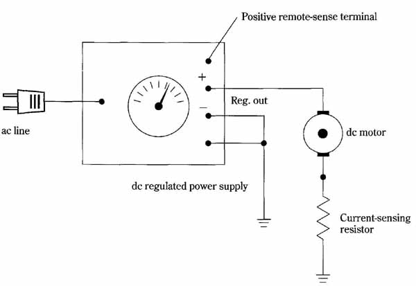
FIG. 15 Using a dc regulated power supply to produce constant torque
in a dc motor. The regulated supply is caused to operate in its constant-current
mode. In the interest of efficiency, the current-sensing resistor should
be as low as possible.
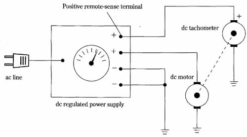
FIG. 16 Using a dc regulated power supply to produce constant speed
in a dc motor. The dc tachometer is a small PM generator mechanically
coupled to the motor. Positive remote-sense terminal; ac line; dc regulated
power supply; Positive remote-sense terminal; ac line; dc regulated power
supply.
