AMAZON multi-meters discounts AMAZON oscilloscope discounts
.For many years, a popular speed control for heavy-duty series motors was a manually-actuated selector of resistance elements. For example, the motorman’s controller used in street cars was just such a device. Despite its brute-force approach and maintenance problems, such a system actually works quite well and now merits reconsideration in applications to electric automobiles. A refinement of such a speed control method is shown in FIG. 14. The basic simplicity of resistance selection is retained, but speed control is achieved with much less power dissipation. This is of paramount importance in a vehicle that carries its own battery energy source.
In FIG. 14 the SCR can be pulsed on and off at a controllable duty cycle. When in its conductive state, the electrical losses of the SCR are relatively low—much lower than would be dissipated in “ohmic” resistance required to produce the same motor performance. The greater the duty cycle of the SCR, the more it effectively shunts current around a portion of motor resistance, such as R3. If the SCR duty cycle is adjusted for 1800, it behaves as a closed switch, essentially shorting whatever resistance it’s connected across. These facts can be deployed in a clever way to accomplish a large range of smooth speed control.
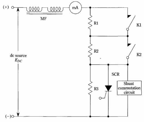
FIG. 14 Series-motor speed control via resistance modulation. The SCR
functions as a chopper to periodically short a portion of resistance
in the motor circuit. Variation of the chopping rate yields a considerable
range of smooth speed control.
Suppose , for example, the motor is moderately loaded and the SCR is continually in its off state. Because of the overall resistance in the motor circuit, you might assume the motor to be at standstill. If then, the SCR is triggered to provide fixed-duration closures at a low repetition rate, the average value of motor current will be increased because of the periodic shorting out of resistance R3. The motor will start and turn slowly. Increasing the trigger repetition of switch K2 will provide an additional range of speeds enabling faster motor operation. Finally, closure of switch K1 allows the third, and highest speed range to be obtained. Various links between the shorting switches and the SCR trigger source can be implemented for convenience and smoothness of control. The scheme is reminiscent of the formerly used series- motor control box in street cars, but the SCR pulsing technique yields better efficiency than in the older schemes that relied completely on dissipation in resistance elements. Of course, some kind of commutating scheme must be provided in order to turn off the SCR if a “pure” dc source is used. Self commutation can be realized with unfiltered half-wave, or possibly full-wave source current from a rectifier.
If the motor is not too large, it would be easier to implement this motor control concept with bipolar power transistors or with power MOSFETs. Then there would be no commutation problem. Such control devices could be paralleled to accommodate the current demands of fractional-horsepower motors. In particular, power MOSFETs lend themselves well to paralleling; no ballast resistances are needed to bring about equitable current divisions between paralleled devices, and unlike bipolar types, there is no “built-in” tendency towards thermal runaway.
In this control scheme, a somewhat different procedure might be necessary for heavy motor loads. Under such conditions, it would be more appropriate to start with switches K1 and/or K2 already closed. The basic idea would then be to provide high initial starting current for the motor. As the motor comes up to speed, either or both of these switches could be opened. The exact control procedure would depend on the desired acceleration and ultimate speed of the motor. Also, somewhat different procedures might prove more appropriate for shunt or permanent magnet motors than for series motors. The series inductance, MF, is not always needed, but is helpful in preventing excessively large surge currents during startup, and with heavy motor loads.
