AMAZON multi-meters discounts AMAZON oscilloscope discounts
There are many applications for dc motors where control of speed and direction is important, but it’s satisfactory to allow speed regulation to be that produced by the natural characteristics of the motor. Thus, the control circuits shown in Figs. 6-12 and 6-13 don’t make use of feedback. The circuit in FIG. 12 is intended for shunt motors, but will also accommodate permanent-magnet motors because reversal is accomplished through change of polarity of applied armature voltage. The circuit in FIG. 13 is intended for series or universal motors. These circuits are predicated upon classical principles of dc motor control, but don’t use rheostats for reducing applied armature voltage. Instead, SCRs are used in a form of phase control. How this can be done and still deliver dc to the motors will be explained. Although components and semiconductor devices were chosen to comply with the needs of 1/15-hp motors, the circuits can readily be “beefed up” to accommodate larger fractional- horsepower machines.
Consider first the circuit in FIG. 13. Note the connections of armature and series field relative to the bridge arrangement of SCRs. Current flow through the armature will always be in the same direction. However, the direction of current flow through the series field depends on whether conduction is provided by SCR1 and SCR4, or by SCR2 and SCR3. Thus, the direction of rotation is determined by the set ting of switch Si because it selects one or the other of these SCR pairs for triggering into conduction.
Speed control is achieved by timing the conduction through the selected pair of bridge SCRs. This is accomplished without any commutation problems. No filter capacitor is associated with the rectified dc from the diode bridge, D1, D2, D3, and D4. This is neither an oversight, nor a cost-cutting technique. Rather, the pulsating dc waveform from full-wave rectification is important in the operation of the circuit. It’s because of the pulsating waveform that “natural” commutation takes place in the SCRs. If dc or nearly-pure dc were used, some means of periodically turning off the SCRs would have to be devised. There are circuits that operate in this way, but they often prove to be critical and unreliable. Failure to commutate SCRs can, at best, result in loss of control; at worst, serious damage can occur to the SCRs, or to the load.
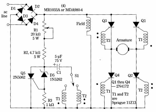
FIG. 12 Control circuit for shunt and permanent-magnet motors. Change
in direction of rotation is brought about by reversing armature current.
Motorola.
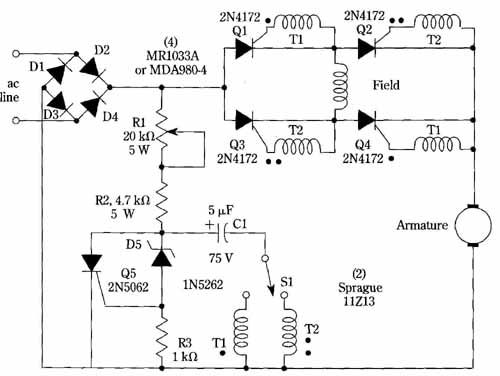
FIG. 13 Control circuit for series and universal motors. Commutation
of the SCR’s ensues from the periodic zeroing of the full-wave rectified
dc. Motorola.
It’s interesting to trace out how the motor-control SCRs are triggered This occurs as a consequence of capacitor C1 charging until it develops sufficient voltage to cause conduction through zener diode D5. This forward biases the gate of SCR Q5, causing the SCR to fire. The resultant pulse is then transferred either through pulse transformer Ti or T2, depending on the position of forward reverse switch Si to the appropriate pair of motor-control SCRs (Q1 and Q4 or Q2 and Q3). SCR Q5 is then commutated (turned off) when its rectified anode-cathode voltage dips to zero. After commutation, a new cycle of events commences with the recharging of capacitor C1. Note that Q5 is commutated in exactly the same way as are the motor-control SCRs. Thus, any filtering at the output of bridge rectifier, D1 through D4, would be detrimental to the operation of the circuit.
Potentiometer R1 enables the speed of the motor to be controlled. The greater its resistance, the longer capacitor C1 requires to develop sufficient voltage to trigger SCR Q5. Inasmuch as this then reduces the conduction time of the motor-control SCRs, the motor experiences reduced voltage and runs slower. The converse situation applies when the resistance of R1 is lowered; the motor control SCRs then con duct earlier in the ac cycle and conduct for a longer time. This increases the effective voltage impressed on the motor and it therefore runs faster.
The operation of the shunt and permanent-magnet motor control circuit of FIG. 12 is essentially similar. When a shunt motor is used, no attempt is made to control the voltage applied to the shunt field; motor control is achieved via control of armature voltage. When a PM motor is used, there is no field winding. But control remains by means of the voltage applied to the armature terminals. Reversal of rotation in this circuit is brought about by reversing the direction of current flow through the armature. This contrasts to the reversal technique used for series motors in FIG. 13 where reversal is attained by changing the direction of current through the series field.
