AMAZON multi-meters discounts AMAZON oscilloscope discounts
Several different types of motors are employed in the different brands of antenna rotators. But whether intended for radio amateurs, CB hobbyists, FM, or TV receivers, the basic control concept of automatic types is quite similar. Automatic operation infers that the system goes into a self-seeking operational mode that terminates when the antenna points in the direction selected by a dial, pointer, or other indicating device in the operator’s control unit. Some of the performance attributes demanded of the motor in the drive unit are high-starting torque, reversibility, and extreme ruggedness and re liability. The dc series motor has excellent torque characteristics. To be reversible, such a motor must either have free access to both series field terminals, or a center-tapped field winding. Permanent-magnet dc motors also have good starting torque and can be readily reversed by reversal of the polarity of the applied voltage. What has been said with regard to the dc series motor also applies to the ac universal motor. Finally, biphase induction motors can be employed much as they are used for garage door actuation.
The most used electronic control technique is that of a bridge in which one arm comprises a variable resistance element mechanically coupled to the antenna. An op posing bridge arm contains a variable resistance mechanically linked to a directional indicating dial or device. The basic idea of this arrangement is that bridge unbalance tends to be corrected as the antenna is driven in the appropriate direction to null the bridge. At null, the power to the drive motor is cut off. Overall, such a system might be described as a position-seeking servo. All manners of electro-mechanical relays, contacts, SCRs and triacs are used in commercial units to perform the various switching functions. FIG. 10 shows a block diagram of a typical automatic antenna rotator.
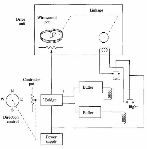
FIG. 10 Block diagram of a typical antenna rotator system. The standstill
torque capability of the drive motor is of paramount importance in such
a positional servo-arrangement.
More insight into the actual implementation of electronic control circuitry is provided by the simplified circuit shown in FIG. 11. In this case, direction reversal is achieved by reversal of polarity in the voltage applied to a dc permanent magnet motor.
In FIG. 11 assume that the system is operational and is in equilibrium, i.e., the directional orientation of the antenna coincides with that indicated on the operator’s azimuth dial. Under this condition, the bridge comprised of resistance elements R1 through R6 is balanced (R7 is in parallel with R6 and is a calibration adjustment). Notice that R2 is the azimuth dial and R5 is mechanically ganged to the motor and antenna shaft. Notice at once that the basic idea is to have R5 driven in such a direction to restore balance to the bridge when such balance is upset by adjustment of the azimuth dial. Another design objective is to have the motor turned off when the antenna points in the direction indicated by the azimuth dial.
Suppose that the azimuth dial is turned in such a direction that the resultant bridge unbalance causes transistor Q2 to be cut off because of the bridge voltage applied to its base-emitter circuit. Then transistor Q1 will also be biased in its nonconductive state. Relay RY2 will be deprived of solenoid current; in turn the motor will be polarized (through the normally connected relay contacts) to rotate in the clock wise direction. This goes on until the bridge approaches balance and Q2 and Q1 are biased into their conductive states. When this happens, relay RY2 is energized, tending to reverse the direction of the motor. However, before this happens, relay RY1 drops out, thereby shutting down the system. The drop out of RY1 occurs during the brief time required by RY2 to change its state. Once this happens, the whole system latches into a quasi-off state, with the motor being deprived of power. This is acceptable because the bridge is then balanced.
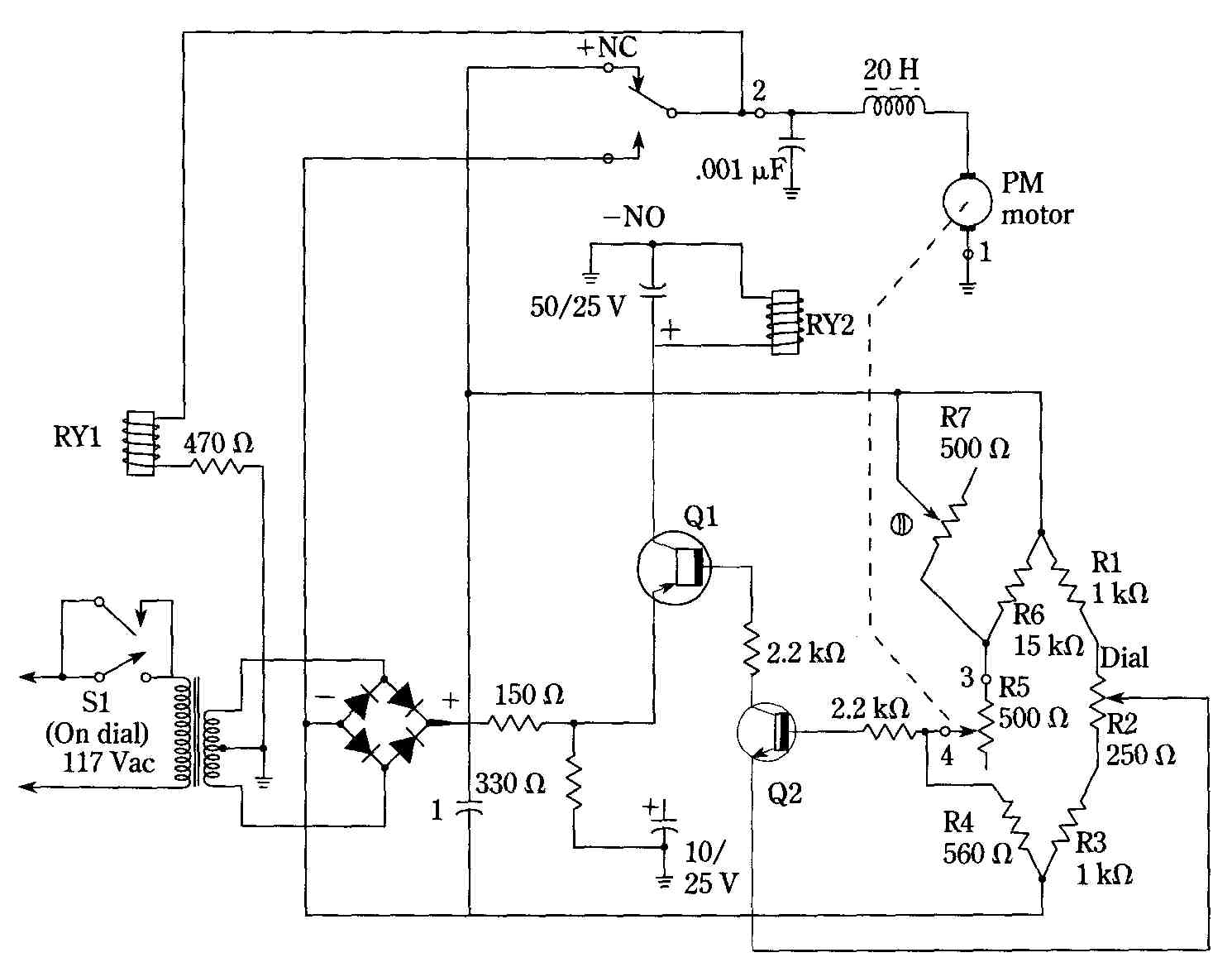
FIG. 11 Electronic control circuit of a typical automatic antenna rotator.
The bridge circuit has one arm mechanically-linked to the antenna; the
opposing arm is controlled by the operator’s azimuth-dial.
If the operator turns the azimuth dial, it not only changes the R2 arm of the bridge, but through appropriate mechanical linkage, it momentarily closes primary switch S1. Once this occurs, RY1 is energized, maintaining primary power until RY2 again undergoes a change of state as bridge balance is approached. Note that a momentary closure of Si suffices to initiate operation; a momentary deprivation of voltage across RY1 when RY2 changes state, suffices to halt operation. The restorative action tending to null the bridge is essentially the same whether the bridge is initially unbalanced in one direction or the other. The basic position-servo techniques long used for rotating amateur and TV antennas are now being adapted for pointing the parabolic dish antennas used for satellite TV earth stations.
