AMAZON multi-meters discounts AMAZON oscilloscope discounts
.Integrated circuit technology and digital logic implementations can be associated with the stepping motor to bring about precise performance and positional control. For many applications, such a system is superior to conventional servo circuitry. For example, because there is no feedback, there are no instability problems. Also, no compromises are needed to avoid overshoot and oscillatory behavior in mechanical members. Best of all the control logic can be achieved via a single IC module. When so done, programming is accomplished with an ASCII keyboard. Sequences of high- level type commands can be stored internally in a program buffer and executed upon command. This is an excellent technique for prototype development. FIG. 4 shows such a system with the CY500 stepper motor controller IC made by Cybernetic Micro Systems. The list of commands that can be stored and/or executed are shown in FIG. 5.
An interesting aspect of this control technique is that the stepping motor can be operated in the half-step mode. That is, it can be sequenced through twice as many discrete positions as would ordinarily obtain from the actual number of physical pole teeth. This, of course, doubles the resolution of the motor.
As an example of the “intelligence” that resides in such a programmable motor system, one could envisage a coil-winding machine in which it’s desired to wind a number of layers of fine wire with a preset number of turns per layer. The process should take place at a known and stable rate—too slow is uneconomical; too fast might break the wire. Appropriate numerical values are selected for “N” and “R” and the programming can allow for repetition of the layer-winding activity until a signal from an external control line actuates the “Q” command to terminate the procedure. Thereafter, the procedure could be repeated, or there could be a return to the command mode. It’s clear that the task would be accomplished in robot-like fashion with uniformity and precision. Although a similar overall routine could be instituted with a linear servo system, one would constantly have to be concerned with erratic torque, drifting limits, and transient conditions. Although “average” performance might be acceptable for reasonable time periods, the fine wire could easily be snapped by a low-level oscillatory condition even though it might be of short duration.
The pin configuration of the CY500 is shown in FIG. 6, and FIG. 7 is a logic diagram of this versatile IC. The parts-count reduction that is realized from incorporating the numerous functions within a single monolithic module is quite dramatic when compared to former control systems. Not only is this device programmable from the ASCII keyboard, but it’s readily commanded from a microcomputer, from an eight-bit data bus, or from data stored in ROM, PROM, or EPROM. Moreover, it’s feasible to incorporate a feedback path so that the stepping motor cannot be commanded to accelerate, reverse, or brake beyond its mechanical abilities. The timing and control signals involved in typical operating modes are shown in FIG. 8. The stepper control signals, PHI1, PHI2, and PHI3 must be power boosted in order to actually drive the four-phase stepper motor. While this can be accomplished with discrete transistor stages, or with power ICs, special modules are available. An example is the Sprague ULN 2813A.
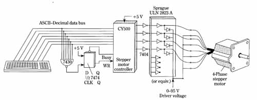
FIG. 4 A prototype system utilizing the CY500 stepper-motor controller.
An ASCII keyboard permits control of such motor-parameters as direction
of rotation, stepping rate, number of steps, repetitive routines, etc.
The most straightforward way to actuate the internal clock circuitry of the CY500 is to simply connect a six megahertz series-resonant crystal to the appropriate pins. However, considerable flexibility exists with regard to the clock function. Crystals with series-resonant frequencies between 1 and 6 MHz can be used. In particular, it might be convenient to use a 3.58-MHz TV color burst crystal. In most in stances, performance will remain satisfactory when these various crystal frequencies are used, but the motor stepping rate must then be scaled down byfl6, where f is the crystal frequency in megahertz. Three clock-circuitry options are shown in FIG. 9.
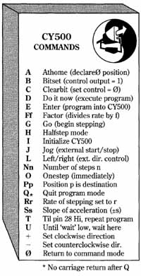
FIG. 5 List of commands that can be stored or executed with the CY500
IC.
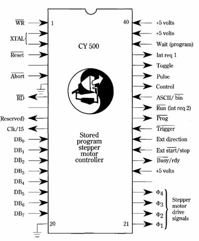
FIG. 6 The pin configuration of the CY500 stored program stepper-motor
controller. A single five-volt supply suffices to operate this device.
Programming information is depicted in simplified form in the CY500 command summary ( Table 1). More detailed explanations of such data appear in the description of commands in Table 2. In using these tables, every command entered consists of one of the following forms:
• Alphabetic ASCII character followed by the ‘)‘ (RETURN) key.
• Alphabetic ASCII character followed by blank, then ASCII decimal number parameter, then)’ = ODH.
Examples of type one are as follows:
Name Command Interpretation
ATHOME A Declare absolute zero location
BITSET B Set programmable output line
CLEARBIT C Clear programmable output line
DO IT D Do program (begin running program)
ENTER E Enter program mode
Examples of type two are as follows:
NAME ASCII Command interpretation
NUMBER N n Declare number of steps to be taken (relative)
RATE R r Declare maximum rate parameter
FACTOR F f Declare rate division factor
SLOPES s Declare ramp rate
POSITION P p Declare target position (absolute)
Table 1. CY500 command summary.
ASCII CODE NAME INTERPRETATION
A ATHOME Set current location equal absolute zero
B BITSET Turn on programmable output line
C CLEARBIT Turn off programmable output line
D DOITNOW Begin program execution
E ENTER Enter program code
F FACTOR Declare rate divisor factor
G GOSTEP Begin stepping operation
H HALESTEP Set half-step mode of operation
I INITIALIZE Turn off step drive lines, initialize system
J JOG Set external start/stop control mode
L LEFTRIGHT Set external direction control mode
N NUMBER Declare number of steps to be taken (relative)
O ONESTEP Take one step immediately
Q* QUIT* Quit programming—re enter command mode. *Not followed by’
R RATE Set rate parameter
S SLOPE Set ramp rate for slew mode operation
T Loop TIL Loop ‘TIL’ external start/stop line
U UNTIL Program waits until signal line goes low
+ CW Set clockwise direction
— CCW Set counterclockwise direction
o COMMAND Exit program execution mode, enter command execution mode
Table 2. Description of commands.
Ae ATHOME 0100 0001 1 byte
The ATHOME instructions (sets the position) defines the ‘Home’ position. This position is absolute zero and is reference for all POSITION commands. The ATHOME command must not be immediately preceded by a change-of-direction command. Note also that the ATHOME command should not be used twice unless the CY500 is reset or initialized between commands.
B1 BITSET 0100 0010 1 byte
This instruction causes the programmable output pin (#34) to go HIGH. This is a general-purpose output that may be used in any fashion.
C CLEARBIT 0100 0011 1 byte
This instruction causes the programmable output pin (#34) to go LOW. The user can signal locations in a program sequence to the external world via B and C instructions.
Di DOITNOW 0100 0100 1 byte
This instruction causes the CY500 to begin executing the stored program. If no program has been entered, the controller will return to the command mode. If the program exists, the controller will begin execution of the first instruction in the program buffer. If the run (DOITNOW) command is encountered during program execution, it restarts the program (however, the initial parameters, and modes, may have changed) and may be used for looping or cyclic repetition of the program.
El ENTER 0100 0101 1 byte
This instruction causes the CY500 to enter the program mode of operation. All commands following the ENTER command are entered into the program buffer in sequence.
F FACTOR f 0100 0110 2 bytes
b7 b0
The FACTOR command causes the rate to be decreased by the factor (1 The factor, f, is a number from 1 to 255.
Go command 0100 0111 1 byte
The GO command causes the stepper motor to step as specified by the rate, direction, etc., commands entered prior to the GO command.
HI HALFSTEP command 0100 1000 1 byte
The HALFSTEP command causes the CY500 to enter the half-step mode and remain in that mode until the device is reset or re-initialized.
I INITIALIZE 0100 1001 1 byte
The INITIALIZE command causes the CY500 to enter the command mode. None of the distance or rate parameters are altered. Any commands following ‘I’ will be executed with the parameters specified prior to ‘ I.’ The INITIALIZE command, when encountered during program execution, halts the program execution and returns the system to the command mode. This command de-energizes the stepper motor coils.
J JOG 0100 1010 1 byte
The JOG command places the CY500 in the external start/stop control mode; i.e., the starting and stopping are controlled by external hardware instead of by software (via the GO command). The ‘J’ command is the last command applied after the step rate, mode, and direction have been specified. However, new commands may be entered when the XSS pin is low. It’s NOT necessary to use the GO command. The application of a low voltage to the XSS pin causes the motor to begin stepping and continue stepping as long as pin #28 is low. Note that the ‘J’ command and the ‘T’ command are mutually exclusive. Either one or the other, but not both, may be used.
LI LEFT/RIGHT pin enable 0100 1100 1 byte
This instruction places the CY500 in the external direction control mode. In this mode, the External Direction Pin (#29) is used to determine the direction, either clockwise (1) or counterclockwise (0). Software commands ‘+‘ and ‘—‘ are ignored in this mode. Any change of control signal applied following the output pulse will be used to determine the direction of the next step.
Nn NUMBERofsteps 0100 1110 3bytes
aT aO LS bytes
b7 bO MS bytes
The NUMBER command is used to specify the number of steps to be taken in the ‘Relative’ mode of operation. The argument may be any number from 1 to 64K. Note that this parameter is stored as 2 bytes in the program buffer. An ‘N’ command immediately following the ATHOME command will take one step less than the specified number. (Note: current devices don’t work correctly for n=multiple of 256. This will be corrected in the next batch of parts. Current devices do, however, treat all POSITION parameters correctly.)
01 ONESTEP 0100 1111 1 byte
The ONESTEP command is used to take a single step. The steps are untimed, and the step rate is determined by the rate at which ‘0’ commands are received. In addition, each step may be triggered externally via the TRIGGER pin.
PI POSITION 0101 0000 3bytes
a7 aO
b7 bO
The POSITION command declares the ‘Absolute’ mode of operation. The argument is treated as the target position relative to position zero. The ATHOME command can be used to define position zero.
Q QUIT (Programming) 0101 0001 1 byte
NOTE: The QUIT command is self-terminating, and should NOT be followed by the Linend ‘1’.
The QUIT command causes the CY500 to exit the ‘Programming’ mode of operation wherein instructions are stored in the program buffer in the order received, and to return to the ‘Command’ mode of operation in which instructions are executed as they are received. Note that the ‘Q’ command is not terminated with the Linend character, Q I ,and such termination may result in incorrect operation. The QUIT command is also used after program completion prior to entering new parameters.
R r RATE rate 0101 0010 2 bytes
b7 bO
The RATE instruction sets the rate parameter that determines the step rate. The rate parameter, r, varies from 1 to 253 corresponding to step rates from 50 to 3350 steps / sec (assuming a rate factor of 1 and a 6 MHz crystal). The rate is nonlinear and can be computed from the rate equation. For crystals other than 6 MHz the step rate should be multiplied by f / 6 MHz, where f is the crystal frequency.
SsI SLOPE 0101 0011 2bytes
a? aO
The SLOPE or slew mode of operation is used when high step rates are required and the initial load on the motor prevents instantaneous stepping at such rates. In such cases, the load is accelerated from rest to the maximum rate and then decelerated to a stop. The user specifies the distance of total travel (via ‘N’ instruction), the maximum rate (via ‘R’), (FACTOR is forced to 1 automatically), and the ramp rate or change in rate parameter from step to step. When executing in the SLOPE mode, the CY500, starting from rest, increases the rate parameter by ‘s’ with each step until the maximum (slew) rate is reached. The device computes the “re-entry” point at which it begins decelerating (with acceleration = —s) until it reaches the final position. NOTE: The user is responsible for ensuring that N>2 (maxrate).
T loop TIL 0101 0100 1 byte
The ‘T’ command provides a ‘Do . . . While . . .‘ capability to the CY500. This command tests pin 28 and, if low, it executes the DOITNOW command, i.e., it runs the program from the beginning (although using the latest rate, position, etc., parameter). If pin 28 is high, the next instruction is fetched and executed. Note that pin 28 is also uspd for external start / stop control when ‘J’ (JOG) is executed. ‘T’ and ‘J’ are therefore mutually exclusive and cannot be used together.
Example: Loop TIL command use.
Enter parameters before running program (optional)
‘D’ executed from external host or keyboard
Execute stored program using latest parameters
Test pin 28 arid run program from beginning if pin 28=LO, else continue executing program
FETCH NEXT
INSRUCTION
IN PROGRAM
FETCH NEXT
INSRUCTION
Loop thru program
“U” = WATT UNTIL
Example: wait UNTIL command use.
U wait-UNTIL 0101 0101 1 byte
The wait-UNTIL instruction is used to synchronize the program execution to an external event. When the ‘U’ instruction is executed it tests the WAIT pin. When the WAIT ph goes high, the next instruction is fetched from the program buffer and execution proceeds.
+ CLOCKWISE command
0010 1011 1 byte
All steps following this command will be taken in a clockwise direction.
— CCW command
0010 1101 1 byte
All steps following this command will be taken in a counterclockwise direction.
0 COMMAND mode 0100 0000 1 byte
The CY500 is placed in the command mode and the next command is executed as it’s received.
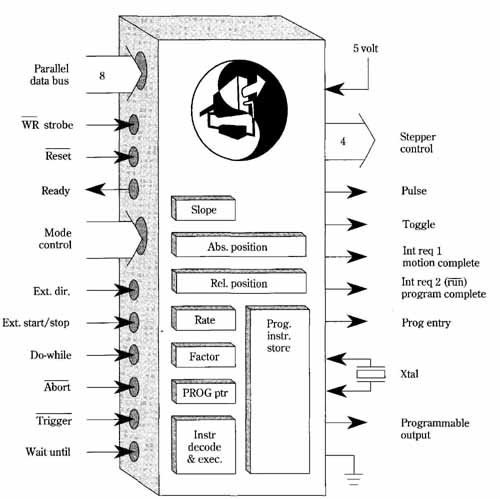
FIG. 7 Logic diagram of the CY500 stored program stepper-motor controller.
The stored program capability is 18 hi-level instructions
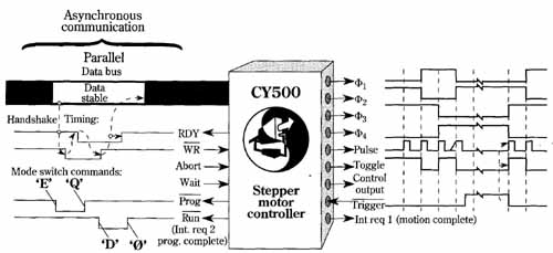
FIG. 8 Timing and control signals in the CY500. Asynchronous communication
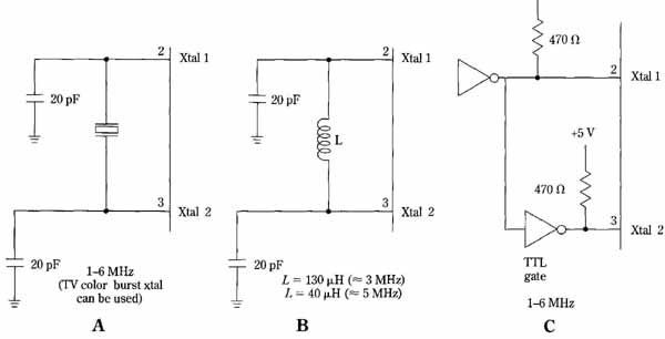
FIG. 9 Three methods of generating the clock signal for the CY500.
(A) Series-resonant crystal. Preferably 6 MHz, but frequencies between
one and 6 MHz can be used. (B) LC circuit. (C) External.
