AMAZON multi-meters discounts AMAZON oscilloscope discounts
.The permanent-capacitor, split-phase motor is particularly attractive for the application of electronic control. This motor has electrical symmetry and operates smoothly from a two-phase power source. One way to obtain speed adjustment is to vary the applied voltage. This scheme exploits the slip characteristic of the motor. Although the permanent-capacitor, split-phase motor permits an inordinate amount of slip to take place, this control technique suffers from the disadvantage that the torque capability decreases along with the speed. Indeed, the torque is directly proportional to the square of the applied voltage; except for very light loads or for fan and blower applications, this type of speed control is often not as practical as one might initially suppose.
A variable-frequency power supply is a better speed-control method. In principle, a wide speed variation should be possible without the plague of “torque-starved” operation. However, it’s clear that the capacitance would have to be continuously variable along with the applied frequency. At best, some kind of compromise could be made so that several capacitors could be selected by a tapped switching arrangement. This, of course, discourages the implementation of a wide speed-control range in such a system.
A better approach is to dispense with the capacitor(s) and to utilize logic circuits to establish the required 90-degree phase displacement regardless of frequency. This is done in the scheme represented by the block diagram of FIG. 12. Linear, digital, and optoelectronic techniques are employed. This is an open-loop system and the motor speed is controlled by adjusting the frequency of the oscillator. Because the optical couplers have unilateral transference characteristics, together with high voltage isolation between their input and output circuits, motor transients are clearly isolated from the logic circuits (such transients could arise from sudden load variations on the motor).
The schematic diagram of this controller circuit is shown in FIG. 13. The use of IC modules renders the actual circuit only slightly more complex than the block diagram.
In the ensuing discussion of the overall circuit, it’s suggested that reference also be made to the waveform diagram of FIG. 14. Circuit operation is simpler than one might assume from these numerous waveforms, for many are paired or are image-related waveforms due to the biphase and push-pull aspects of the configuration.
The schematic diagram in FIG. 13 shows a free-running relaxation oscillator using a unijunction transistor, Q1. The oscillator frequency, and therefore the speed of the motor, is adjustable by the 500-kOhm potentiometer in its emitter circuit. This oscillator has a frequency range of approximately 40 Hz to 1200 Hz, but subsequent logic operations divide the frequency down to the 10-Hz to 300-Hz range. This corresponds to a speed range of 300 RPM to 9000 RPM if a two-pole motor is used.
Transistors Q2 and Q3 are essentially waveshapers. They process the output from the UJT oscillator to a suitable waveform for actuating the set-reset input circuits of the “X” flip-flop within the MC688 IC. This flip-flop is the R-S type—its operation depends on the input levels and their duration, rather than their rise and fall times.
The Q output of the “X” flip-flop is designated as X in both the schematic and the waveform diagrams. The X waveform clocks the “A” flip-flop, which is also within the MC688 IC. The “A” flip-flop performs as a divide-by-two toggle and provides two clock signals, which are 180° out of phase. These clock signals are applied to the “B” and “C” flip-flops.
The “B” and “C” flip-flops toggle on the negative transitions of their input clock signals. At the same time, these flip-flops divide their input clock rates by two. A comparison of output wave trains from flip-flops “B” and “C” shows a phase displacement of 90°. Significantly, this quadrature phase relationship—contrary to that associated with capacitor circuits—is independent of frequency. It would now appear that all that need be accomplished is a power-level boost of the quadrature out put waveforms. Although this might suffice, an additional refinement is desirable.
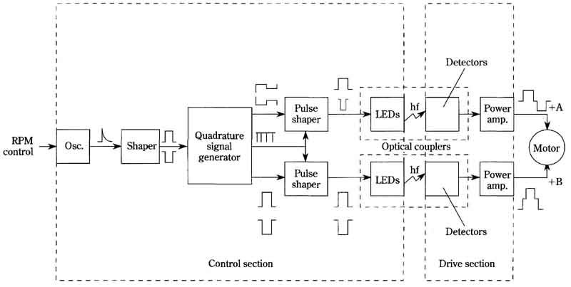
FIG. 12 Block diagram of speed control for permanent-capacitor spilt-phase
motor. Control section; Drive section
In each channel, push-pull power transistors provide the required ac power for the two-phase motor. The operating efficiency of such push-pull amplifiers can be increased if provision is made for turning off both transistors during the polarity transitions. Otherwise, there will be high dissipation when the two transistors are forced into simultaneous conduction during crossover, because of their inability to turn off instantaneously. The reason for such occurrence is that turn-off time is generally slower than turn-on time. Cutoff during crossover is produced iii the following manner:
The MC673 ICs contain a dual set of two input of NAND-NOR gates. These gates enable the B and C waveforms to be mixed with pulse trains derived from the “X” and “A” flip-flops in such a way that zero-voltage steps are generated in the final waveform. These zero-voltage steps occur during the intervals when the push-pull output transistors must alternate their conductive states. The zero-voltage steps are clearly seen in the A and 1B motor-drive waveforms. These “rest periods” for the power transistors are actually only about twenty microseconds in duration; they rep resent a very minor distortion of the essentially square waveforms.
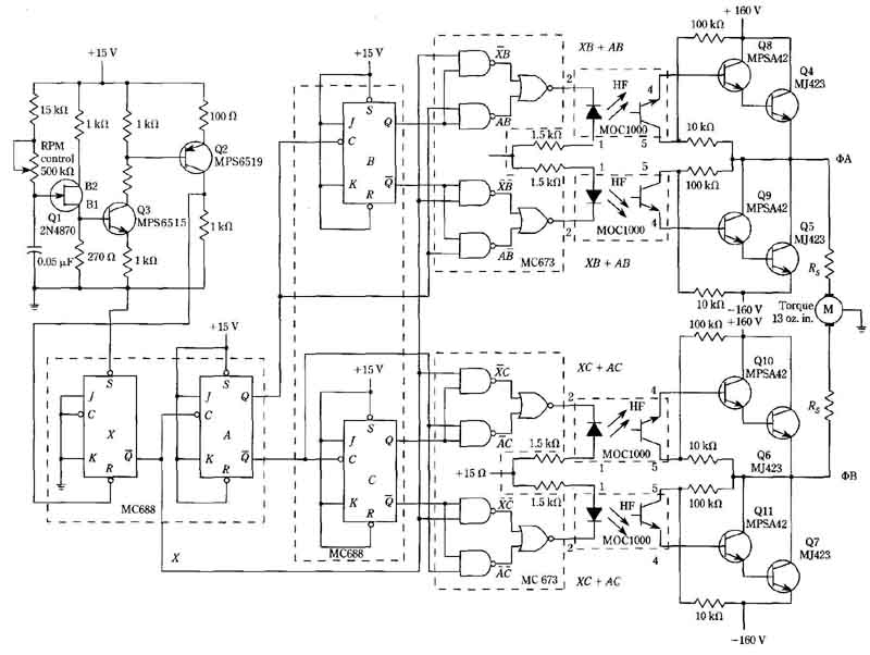
FIG. 13 Schematic diagram of speed control for permanent-capacitor,
split-phase motor.
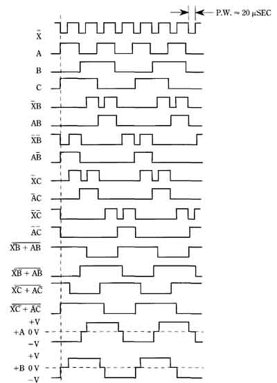
FIG. 14 Waveform diagram for speed-control circuit in FIG. 13. Motorola
Products, Inc.
The resistances R in series with the stator windings of the motor, limit its current. Such limiting is necessary to compensate for the change in the reactance of these windings when the frequency of the applied voltage is changed. For a motor with a nominal torque capability of 13 ounce-inches at a speed of 1700 RPM, the value of these resistances is 25 ohms with a 50-watt power dissipation rating. Be cause of the need for these resistances, this control scheme appears best adapted to small fractional-horsepower motors. However, if the motor supply voltage is varied with motor speed, larger motors can be efficiently controlled.
When “off-the-shelf” motors are operated from an essentially square-wave source, a higher than normal temperature rise is often observed, even at 60 Hz. This is because of the added hysteresis and eddy current losses due to the harmonics in such a nonsinusoidal power source. The third and fifth harmonics, because of their relatively high amplitudes, tend to be the chief culprits. Either improved heat removal or lower horsepower can be invoked as remedial measures. On the positive side, no efficiency or torque is lost in this system from imperfect quadrature relationship of the two phases.