AMAZON multi-meters discounts AMAZON oscilloscope discounts
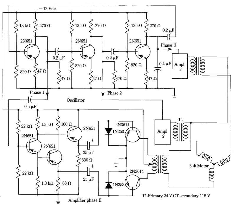
.In contrast to the digital logic system shown in FIG. 9, an analog three-phase generator is shown in FIG. 11. This circuit produces square waves because the output transistors are driven into their saturation regions. The power capability is on the order of 150 - 250 watts, total. The 400-Hz frequency is fixed. Both motors and trans formers have significant size and weight advantages at this frequency, compared with 60-Hz components.

FIG. 11 Analog three-phase generator. By Motorola.
The oscillator is essentially a three-stage RC-coupled amplifier with a feedback path from the output to the input. Oscillation takes place at that frequency, which allows a total phase shift of 360°. This implies a 120-degree phase displacement per stage, which corresponds to the phasing of a three-phase power line. Therefore, an output from each stage of the oscillator is used to drive an amplifier, culminating in push-pull power output stages. In order to simplify the presentation, the schematic diagram of FIG. 11 shows only one of the three identical power-amplifier channels; the other two are shown as function blocks. The first stage operates as a phase splitter in order to develop the 180-degree out-of-phase signals for the push-pull circuitry. In this way, input transformers are avoided. Emitter-follower drivers then interface this phase-splitting stage with the power-output transistors.
This technique is excellent for applications demanding a respectable ratio of horsepower to size and weight, such as in aircraft, space vehicle, and marine work. Control flexibility is not as good as that obtained with digital polyphase systems, how ever. To get a speed-control range, substitute a three-ganged assembly of 1000-ohm potentiometers for the 820-ohm resistors. The wiper of each potentiometer would then connect to the coupling capacitor feeding the base of the transistor associated with that potentiometer. The idea is to vary the time constants without changing the transistor bias networks. This, alone, will provide higher frequencies and greater motor speeds. If lower speeds are also desired, the 0.2-uF coupling capacitors should be in creased in size. If the oscillator frequency is reduced more than about 15 percent of the nominal 400 Hz, an arrangement should be made to simultaneously reduce the voltages applied to the motor.
Sine-wave operation of this system could be achieved by increasing the value of the 47-ohm emitter resistances in the three oscillator stages. However, efficiency of the power-output transistors would then be reduced from approximately 90 percent to approximately 70 percent.