AMAZON multi-meters discounts AMAZON oscilloscope discounts
..The arrangement illustrated in FIG. 6 is a solid-state relay circuit for three-phase inductive loads, such as induction motors. On and off control of the motor is affected by a low-level logic signal applied to the input of the system. Optoelectronic devices are used in the input circuits for electrical isolation between the control logic and the three-phase power circuitry. It can be appreciated that turning a large polyphase motor on and off is not a trivial problem. Mechanical or electromechanical devices are bulky, expensive, and high maintenance prone. Moreover, the arcing associated with physical contacts generates RF interference and constitutes a hazard in some operating environments.
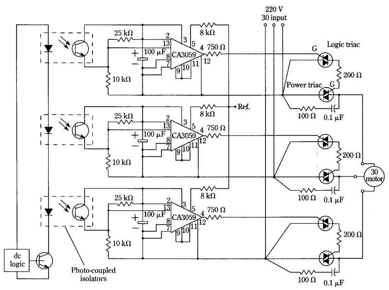
FIG. 6 Triac control circuit for three-phase induction motors. RCA.
The CA3059 IC modules are actually zero-voltage switches—that is, they have the property of providing triac gate pulses only when the voltage wave of one of the three phases crosses its zero axis. Such thyristor triggering results in minimal RFI. However, these IC modules are not employed in their usual fashion in this circuit. It’s not necessary, or desirable, to attempt zero-voltage switching when the load has appreciable inductance. The inductance, itself, prevents abrupt current transitions on “make” (the slowed down current buildup serves as an RFI preventative). The connections between terminals 7 and 12 on these IC modules render their operation similar to that of a differential op amp with sufficient output capability to reliably trigger triacs. When the incoming logic signal is “high,” the output from the three IC modules are sustained dc drive voltages that trigger their respective logic triacs. In turn, the logic triacs gate the motor-controlling power triacs. As is the nature of all thyristors, the triacs automatically commutate to their off states when their ac cur rents approach zero in the progressing sine waves. Providing that the input logic re mains high, each triac is retriggered twice per cycle of its phase voltage.
Inasmuch as a single logic signal controls the entire three-phase motor circuit, it’s easy to associate various types of sensors with the input circuit so that the motor can be automatically turned on or off at certain temperatures or under other conditions. Similarly, timing circuits can be readily arranged to initiate or terminate motor operation when desired.