AMAZON multi-meters discounts AMAZON oscilloscope discounts
.Use of the stepper motor is not the only way to devise a speed/position control system. A PM dc motor can also be made to obey speed commands and to stop precisely at a predetermined position. This enables greater torque and power than is readily attainable from stepping motors. At the same time, very high resolution is possible. What is needed is a shaft-mounted optical encoder and some special electronics. The latter requirement can be conveniently satisfied with several “building-block” dedicated ICs, and a microprocessor or microcomputer. Overall, a servo-positioning system results that benefits from closed-loop sensing and response (stepper motor positioners are conventionally open-loop systems).
The optical encoder is a special type of tachometer that generates more information than merely pulses proportional to speed. The nature of the encoder is illustrated in the sketch of FIG. 25. Notice that there are two slotted disks, a stationary one, and one rotated by the motor shaft. This is essentially a light-chopper technique. The slots in the two disks overlap so that two quasi sine-wave signals are generated that have a 90-degree phase relationship. The frequency of these signals represents the speed of the motor, and their plus or minus 90-degree phase relationship conveys directional information. Additionally, a third signal of one pulse per revolution is generated in order that the absolute position can be found at initialization. The quasi sine-wave signals are designated as the FTA and FTB signals. The pulse-per-revolution signal is termed the FTF signal.
The block diagram of the speed/position control system is shown in FIG. 26. The salient aspect of such a scheme is what could otherwise be a very complex array of electronic circuit schemas are made quite simple and straightforward with the use of the three dedicated ICs.
The operating modes of the control system can be gleaned from inspection of FIG. 27. When first started, the system is in its speed-control mode; however, at startup, the tachometer signal is either absent at zero-time or relatively small during acceleration. During this interval, the system is effectively operating open loop, enabling a high starting current. This is desirable because it promotes rapid speed buildup. Once the motor attains its preset level of speed, closed-loop speed regulation sets in and the speed of the motor is held constant.
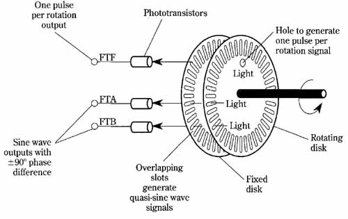
FIG. 25 Optical encoder for enabling a dc motor to operate as a servo
positioner. Two 90-degree displaced signals are generated together with
a one-pulse-per-revolution signal. One pulse per rotation output; Sine
wave outputs with ± 90 degree phase difference.
Later, when the microprocessor commands deceleration in preparation for stop ping at a predetermined position, the motor is progressively braked, reducing its speed. Finally, the system is commanded to switch to its position-feedback mode. The motor then stops abruptly at the desired position and is held there by an electronic detent.
The schematic diagram of the dc motor speed/position control system is shown in FIG. 28. Aside from the addition of a few passive components, it’s almost as simple as the block diagram of FIG. 26. The apparent complexity that one sees at first glance stems from the depiction of the internal circuit functions of the three-dedicated ICs. It turns out that this draftsman technique is useful in analyzing the operating principles of the overall system. In particular, the circuit-point designations shown inside of the L290 coincide with the waveforms designations of FIG. 29.
Further assistance to circuit analysis is provided by the unique parts list of Table 1. Each part is accompanied by a brief statement indicating its purpose in the schematic diagram.
Hole to generate one pulse per rotation signal
Table 1. Parts list and their circuit functions. The designations of the parts coincide with those shown in the schematic diagram of FIG. 28.
A word is in order regarding the switching frequency of the L292 switchmode motor driver. This is governed by timing components R20 and C1. The best frequency will usually be found to be in the 16-kHz to 23-kHz range, where optimum balance between low noise and high switching efficiency is likely to be realized. How ever, capacitor C1 also sets the delay time that protects against simultaneous conduction of the output transistors. The suggested value of C is 1.5 nanofarads. This dc motor speed/position control system results in a protective switching delay of about 2.5 microseconds—more than adequate. A further stipulation in selection of the RC timing values is that R must be at least 8.2 k-Ohm. These restrictions allow sufficient flexibility in attaining optimum operation. The actual switching frequency will be approximately:
f_osc. = 1 / [(2)(R_20) (C_17)]
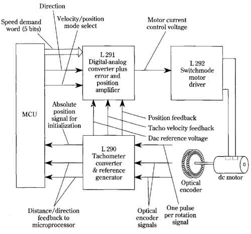
FIG. 26 Speed/position control system for a dc motor. The dedicated
ICs used in this scheme en able operation from an ordinary dc PM motor
to simulate that of a stepping motor, but with possible advantages of
torque and power. Very high positioning precision is another plus feature.
Under most circumstances it’s better to purchase, rather than construct, the optical encoder. A suitable one is the Sensor Technology STRE 1600, which has 200 slots. Similar types are available from Sharp Electronics Corporation.
Although the nominal 2-ampere, 36-volt output of the L292 driver is a respectable power level for an IC, it’s understandable that greater drive for larger motors might be needed. The best approach is to insert the required high-power stage between the L292 and the larger motor. In that way, the basic operating mode of the described system won’t be altered. Because of the relatively low switching frequency, bipolar transistors, (including Darlingtons), power MOSFETS, and IGBTs all merit consideration as output devices. Low-inertia motors such as the pancake or printed-circuit types are best suited in position-servo systems.
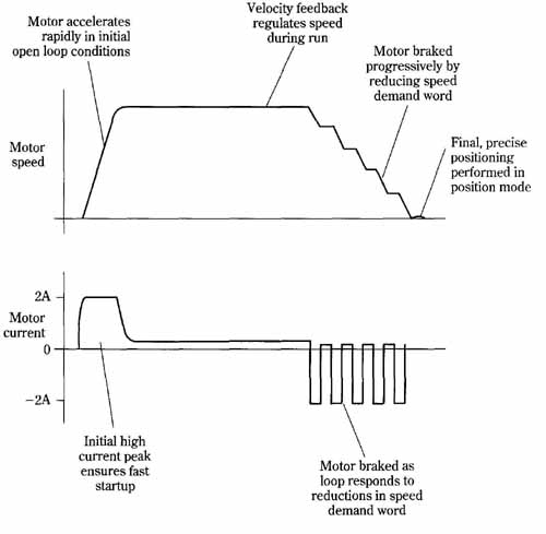
FIG. 27 The operating modes of the dc motor speed/position control
system. Tachometer-feed back regulates the speed during a run. It also
provides for deceleration upon approach of the target position. Finally,
position-feedback enables the motor to stop at the programmed position.
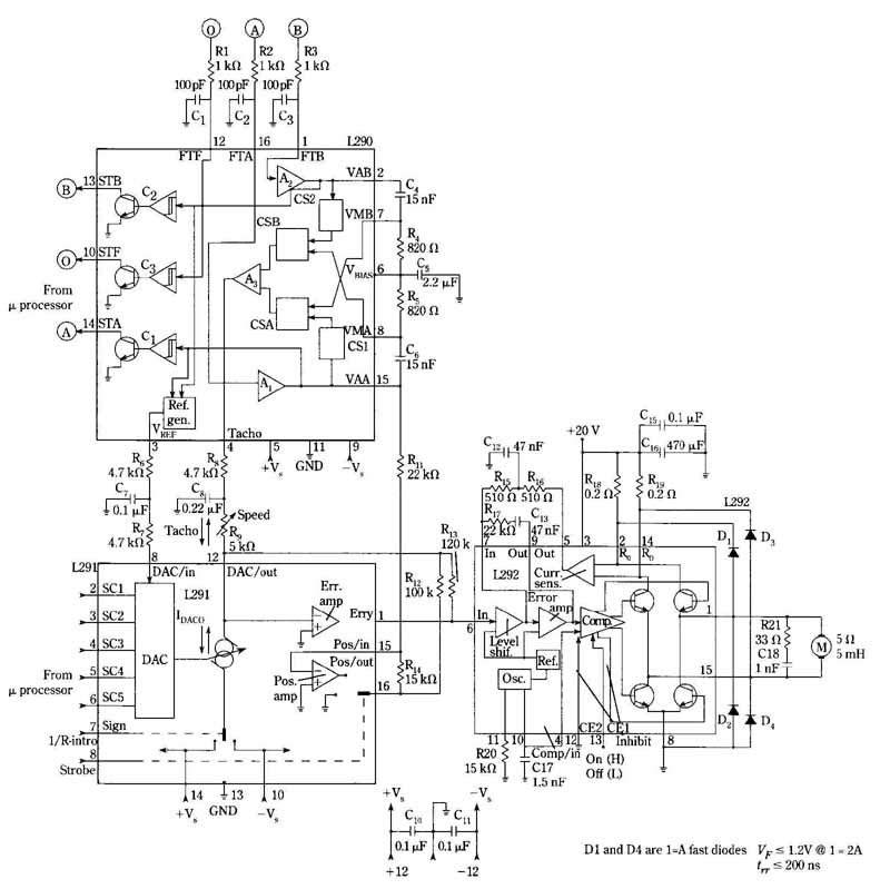
FIG. 28 Schematic diagram of the dc motor speed/position control system.
The functional components of the three building-block ICs are shown to
facilitate understanding of circuit operation. Note that the L290 IC
has designated circuit-points that coincide with those listed in the
waveform diagram of FIG. 29.
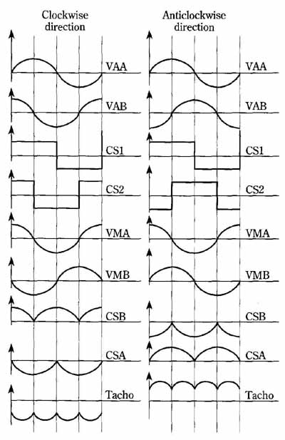
FIG. 29 Waveform diagram of circuit points inside the L290 IC. Note
that the circuit-point designations coincide with those shown inside
the L290 in the schematic diagram of FIG. 28.