AMAZON multi-meters discounts AMAZON oscilloscope discounts
. The non-commutator electric machine has always been favorably assessed for its basic simplicity, with its attendant ease of manufacture, and for its exceptional re liability and relative freedom from radio frequency and electromagnetic interference. Some of these machines do have sliding contacts, but they are in the form of slip rings rather than commutators. Moreover, it’s often true that the currents handled by the slip rings are much lower than those necessarily associated with commutators. Thus, in the automobile alternator, slip rings are used for conducting the field current to the rotor. This current is a small fraction of the charging currents that these alternators must handle. On the other hand, the older commutator-type dc generator used in automobiles had to pass the large charging currents through its commutator. As might be expected, the maintenance problem was far from trivial.
A shortcoming of non-commutator motors, however, was their inability to readily vary their speed over a wide range. Now; with solid-state electronics, this disadvantage is no longer necessary. The new control techniques give old-style non-commutator motors a performance flexibility never dreamed feasible by their original designers.
The following control circuits are interesting because they overcome the performance limitations long held to be inherent in ac machines, particularly induction motors. Also, you can sense the keen competition surrounding the selection of motor types. With the new control techniques, it no longer suffices to consult a motor text, or even motor specifications. To a large extent, you can now electronically “tailor” machine characteristics. Therefore, decisions must be influenced more by other factors, such as cost, reliability, electrical and noise considerations, etc.
Triac speed-control circuit for induction motors
The triac speed-control circuit for induction motors shown in FIG. 1 is similar to that shown here, which is intended for use with universal motors. The circuit in FIG. 1, however, incorporates a single-time-constant circuit to delay the phase of the gate trigger. This simpler approach is permissible because induction motors generally cannot be slowed down enough to get into the troublesome hysteresis area for which the double-time-constant gate circuit is prescribed as a remedy. This speed-control circuit works best for the permanent split-capacitor type of induction motor. The shaded-pole induction motor is also amenable to this control technique. With any type of induction motor, this speed-control technique is most effective when the load is a fan or blower. (A small change in speed produces a relatively large change in air velocity.) Another favorable aspect of such loads is their low starting-torque requirements.
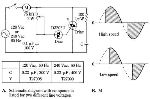
FIG. 1 Triac speed—Control circuit for induction motors. By RCA. (A.
Schematic diagram with components listed for two different line voltages.
B. M)
Resistance-start and capacitor-start induction motors can be triac controlled under certain conditions. Generally it will be necessary to limit the speed-control range; the speed should not be reduced to the point where the centrifugal switch re connects the starting winding or starting capacitor. All things considered, the greatest range of speed control will be obtained with the permanent split-capacitor motor. This type of induction motor is not encumbered with a centrifugal switch. Moreover, it operates well in the high-slip region. A three to one speed-control range is possible with fan loads.
This circuit is greatly superior to the single-SCR, phase-controlled thyristor circuit for use with induction motors. The SCR works well with universal motors, but the dc component developed by half-wave rectification is detrimental to the operation of induction motors.
The RC “snubbing network” connected across the triac does not generally appear in the circuit when the load is resistive, which is the case with lamps or heaters. Because a motor load is inductive, triac turn-off will occur at zero current, but the voltage across the triac won’t be zero at that time. A voltage step is thus developed across the triac that can cause retriggering, despite the lack of a gate signal. This can happen even if the voltage-blocking capability of the triac exceeds peak ac voltage by a comfortable margin. The culprit is not necessarily the magnitude of this voltage step, or “spike,” but rather its rate of change. Triacs specified with a high dv/dt across the main terminals will, other things being equal, tend to reduce the likelihood of such malperformance.