AMAZON multi-meters discounts AMAZON oscilloscope discounts
.The study of electric motors and generators generally begins with DC machines and progresses to ac types. This, like many classifications, is quite arbitrary. Indeed, valid arguments can be readily offered for the reverse treatment of the subject matter. For example, it’s true that the armatures of virtually all dc machines actually carry alternating current. The reason that certain machines are said to be dc types is because they have a commutator. The commutator is a rectifier, or a reversing switch, which adds complexity to a machine. Thus, it would not be unreasonable to study ac machines first and then progress to dc motors and generators.
For the sake of convenience, a classification plan can be adopted for the study of electronic-control applications to electrical machines. Rather than deal with the concept of dc and ac motors and generators, these machines can be treated on the basis of whether or not they have commutators. This is my method of covering circuits and systems discussed in this section and in the next section. I will thereby circumvent the dilemma of deciding the most appropriate way to classify solid-state controllers of universal motors.
This section investigates the electronic control of machines with commutators. The fact that some circuits or systems are intended for operation from dc sources, while others are powered from the ac line, is certainly a point of interest. The primary classification criterion will, however, involve the presence of the commutator.
Speed control of a universal motor with SCR
The salient feature of the speed control shown in FIG. 1 is simplicity. It’s a half- wave system because the single silicon controlled rectifier allows passage of alternate pulses from the power hue. These unidirectional pulses are fractional parts of the alternations—how large a fraction is governed by the time in the ac cycle that the SCR is triggered. This timing is, in turn, determined by the phase shift produced at the junction of C1 and P1 with respect to the cathode of the SCR. Control of this phase shift is provided by adjustment of P1.
Although the motor receives pulsed energy by means of this circuit action, the repetition rate of the pulses is fast enough to develop an essentially smooth torque.
The later the SCR fires in the ac cycle, the less the average current is through the motor. Accordingly, less internal torque is developed and the speed is thereby de creased. In such a half-wave system, the top speed of the motor is less than what it would be if it were connected directly across the power line. This is readily obvious from the following consideration. Top speed would be obtained with the SCR con ducting a full 180° of each ac alternation. But, an SCR operating in this fashion would simulate an ordinary rectifier diode. The motor would then “see” a simple half-wave power source. The half-wave rectification makes 45 percent of the average current available to a load that would be available with a direct connection (the concept of average current rather than RMS values is relevant to motor operation because torque depends on average current). In some applications, a switch is placed across the SCR in order to provide the full-power option for motor operation. Another limiting factor with regard to control range is the inability of the phase-shift circuit to provide the ideal 0- to 180-degree span adjustment.
Even with the low rectification efficiency of half-wave operation, the process occurs with very little energy dissipation. Therefore, motor control by a circuit such as that of FIG. 1 is much more efficient than simple rheostat speed control. Also, the basic speed/torque characteristic of the motor is not appreciably altered. The only important dissipation in the 8CR is that associated with its forward voltage drop, which is relatively low. The overall result is that large motors can be controlled in this fashion with minimal concern for heat removal.
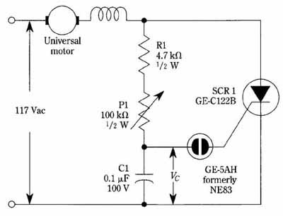
FIG. 1 SCR speed control circuit for universal motors. General Electric
Co.
The neon bulb, because of its high firing voltage, is relatively immune to erratic triggering. This sometimes is an important consideration due to the transients imposed on the line by brush sparking. Although commonplace neon bulbs might suffice for use with very small motors, it’s generally best to use the specially designed units. This is because high current pulses are needed to fire SCRs.