AMAZON multi-meters discounts AMAZON oscilloscope discounts
.When a motor drives a load that is essentially inertial in nature, a long coasting period might ensue when the motor is turned off. This can be undesirable for certain applications. Slowdown by mechanical braking often proves both awkward and costly. Dynamic braking is a much used technique in which the motor is operated as a generator after being disconnected from its source of electrical power. When a machine is functioning as a motor, it develops a counter EMF; when the same ma chine operates as a generator, it develops a counter torque. The more electrical power extracted from such a generator, the greater the countertorque produced in its armature. Therefore, if the armature terminals of a dc motor were immediately shorted following turn-off, a very rapid deceleration of the rotating shaft would be anticipated (j the field remained energized).
In order to spare the armature from undue mechanical stress, as well as electrical stresses on the commutator and brushes, the armature short circuit is not often used. Rather, a low resistance connected across the armature suffices to bring the motor to a quick enough halt. The resistance power rating must be able to absorb the sudden conversion of kinetic energy to electrical energy and dispose of the resultant heat.
FIG. 24 shows a novel electronic circuit that automatically provides dynamic braking when a dc motor is shut off. This circuit is intended for use with permanent-magnet motors but is also adaptable to shunt-wound and some series-wound motors. When switch S1 is in its RUN position, dc power is fed to the motor armature through rectifier D1. The transistor circuit is inactive because the emitter base is reverse biased. When switch S1 is placed in its stop position, the still rotating armature generates a voltage of the same polarity as the power source, insofar as the emitter and collector of the transistor are concerned. The base is, however, now isolated from the emitter because of the unidirectional characteristic of diode D1. This being the case, the base becomes heavily forward biased through resistance R1. Transistor Q1 is driven into saturation and behaves as a closed switch, connecting resistance R2 across the armature. This causes the motor to relinquish its mechanical motion in order to “pay” for the heat energy developed in resistance R2.
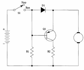
FIG. 24 Automatic braking circuit for DC motors.
If a shunt motor is used, the field must remain energized during the slowdown period. Otherwise, only a negligible reduction of coasting time will occur. A four- terminal series motor can be dynamically braked by this circuit if its field is energized from an appropriate source after the armature is disconnected from the line.