AMAZON multi-meters discounts AMAZON oscilloscope discounts
.The three-phase wound-rotor induction motor exhibits the advantage over other induction motors in that its speed can be adjusted over a considerable range. On the other hand, it suffers the disadvantage in that its speed regulation is poor. That is, a variation in the loading tends to produce a large change in speed. Additionally, the speed-control rheostats in the rotor circuit sometimes waste considerable power. There is a relatively simple way to obtain up to a four-to-one speed range with good speed regulation, and without high-power dissipation. The arrangement shown in FIG. 23 is known as the Kramer drive. A dc shunt-field motor shares the same shaft as the wound-rotor induction motor. Electronic circuitry is limited to rectification in the basic setup.
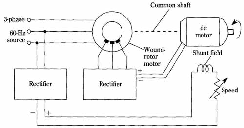
FIG. 23 The speed-control system. The combination of ac and dc motors
coupled to a common shaft provides an efficient adjustable-speed range
with good speed regulation. Speed changes from varying the load on the
output shaft are much smaller than would result from either motor alone.
In this unique scheme, the ac slip-power from the rotor of the induction machine is rectified and delivered to the armature of the dc motor. Speed control of this combination is obtained by adjusting the field current to the dc motor. Inasmuch as field current in a shunt dc motor is, at most, a small fraction of its armature current, there is little opportunity for power wastage. Speed regulation with respect to load change is very good because of a feedback mechanism; suppose that the load is increased, tending to slow the rotation of the shaft. The lower speed increases the slip power of the induction motor, which causes greater current to be delivered to the armature of the dc machine, thereby forcing it to speed up. The net effect is that the shaft speed is considerably stabilized against load changes. Note that both machines contribute torque to the common shaft.
There are other ways of viewing this duo. It bears some resemblance to the con catenation of induction motors described elsewhere. This stems from the scheme of having two motors coupled to a common output shaft. The wound-rotor induction motor can be thought of as a variable transformer with the rotor serving as the secondary. Also, the dc shunt motor performs somewhat as a magnetic amplifier in that the control of low power in its field circuit serves to control high power in its armature circuit. In any event, it’s noteworthy that there are no rheostats in heavy-current portions of the circuit.
The maximum speed of this technique is that of the induction motor. A commonly attained speed range for 60 Hz is 450 to 1700 RPM. The minimum speed is a consequence of the relationship between voltage provided by the rotor of the induction motor and that needed by the armature of the dc motor. This relationship tends to be contradictory to extending the speed-control range much beyond the alluded four to one.