AMAZON multi-meters discounts AMAZON oscilloscope discounts
By means of a unique method, the speed-versus-torque behavior of shunt and permanent-magnet motors can be stabilized to simulate the operation of the ac synchronous motor. At the same time, the basic features of dc machines, such as high starting torque, electrically adjustable speed, and operation from batteries, are retained. An obvious application area is magnetic-recorded equipment. There are also many timing techniques in photography and in industrial instrumentation where such a motor control is required.
FIG. 15 depicts the circuit for achieving such speed regulation. The modification of motor behavior attained with its use is shown in FIG. 16. Note that full torque is available for starting. In the circuit of FIG. 15, the SCR is triggered at periodic intervals by a unijunction relaxation oscillator, Q1. A second feature of the circuit is the cam-actuated switch, S2, which is mechanically coupled to the motor shaft. The following conditions apply:
• The armature current path is either through the SCR or through switch S2.
• The closure of switch S2 not only established the armature current path, but com mutates the SCR. That is, conduction in the SCR is stopped at the closure of S2.
• The primary function of cam-actuated switch S2 is to commutate the SCR— the fact that S2 also provides an alternate armature-current path is incidental. Thus, the shape of the cam is such that the periodic closure of S2 is momentary with respect to its off time.
If a load is placed on the operating motor, its natural tendency will be to slow down. However, such a slowdown results in longer conduction time for the SCR. In turn, this means higher average armature current, which accelerates the motor. The speed correction thus attained won’t be greater than that permitted by the turn-on rate of the SCR. Because this turn-on rate is determined by the oscillator, the motor speed locks to the oscillator frequency. The opposite reactions occur if the motor load is relaxed. Referral to the timing diagram of FIG. 17 reveals that the oscillator frequency and the SCR turn-on rate remain constant over the full range of motor loading. The com of the SCR is, however, modulated in time. At first, the nature of these events might seem to be contradictory. How can the SCR be turned on synchronously with the motor rotation, but be turned off at apparently random intervals?
The answer is that loading of the motor causes a momentary slowing of its instantaneous speed, just enough to enable it to lag farther behind the oscillator while maintaining its average synchronous speed. In other words, the phase displacement between the two ac sources, the oscillator and the motor-actuated switch, widens.
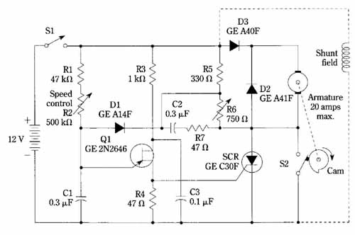
FIG. 15 Synchronous control for permanent-magnet or shunt dc motors.
Genera Electric Co.
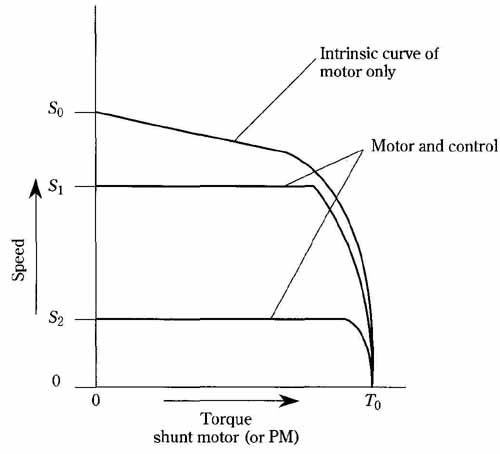
FIG. 16 The effect of synchronous speed control on permanent-magnet
and shunt dc motors. General Electric Co.
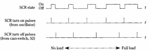
FIG. 17 Timing diagram for synchronous control of a DC motor.
The consequence of this is a longer turn-on time for the SCR, enabling more torque- producing current to be delivered to the synchronously rotating motor. This sequence of events is directly analogous to the operation of an ordinary ac synchronous motor, in which an increased torque demand is satisfied by additional lag of the rotor with respect to the rotating field. The rotor, however, maintains an average speed that is synchronous with the rotating field.
In order to prevent hunting, false locking, and other types of erratic operation, the triggering of the SCR must be delayed when the motor speed is not close to synchronism. This is accomplished by the delaying network comprising R5, R6, R C2, and D1.
Diode D2 is the “free-wheeling” diode commonly found in switching-type power supplies. It provides a current path for the motor armature during off time, thereby smoothing the torque. It also prevents destructive arcing of the cam-actuated switch in this circuit (in other words, D2 provides a useful outlet for the magnetic energy stored in the motor).
The ambitious experimenter might consider the possibility of using a non-mechanical sensing technique. This can be accomplished with optoelectronic methods or by magnetic sensors (both of these suggested sensing approaches can be found in electronic ignition systems for automobiles). It would probably be wise to first obtain satisfactory operation with the mechanical scheme as described. Then, the modification to electronic sensing should prove to be straightforward.