AMAZON multi-meters discounts AMAZON oscilloscope discounts
.A speed-control system cannot be more accurate than the method used for the actual sensing of motor speed. Although there is close correlation between impressed armature voltage and speed, and between counter EMF and speed, there are applications where more precise speed sensing is needed. This is readily attained by coupling a dc generator, or tachometer, to the motor shaft. Thus, a dc voltage representing speed is produced. This voltage can represent speed quite accurately and is not influenced by armature reaction, current, or temperature within the motor itself. Also, the polarity of the tachometer voltage changes with the direction of rotation. This is a fortuitous convenience in bidirectional systems. The tachometer signal is usually fed back to the input of the system where it’s compared with a variable reference, or speed-command, voltage. The comparison produces an error voltage of the polarity required to extinguish itself by correcting the motor speed. And, as long as the speed-command voltage is held constant, the motor speed will be maintained constant despite variations in mechanical load or in other motor operating factors.
FIG. 13 is a block diagram of a speed-control system using tachometer feed back. There are other feedback loops as well. These are for the purposes of linearizing overall response, increasing bandwidth, and limiting motor current. The tachometer feedback loop embraces all the amplifier stages and therefore is instrumental in determining motor speed. The system shown is intended for use with either a permanent-magnet motor or a shunt motor. With a shunt motor, the high end of the speed range can be extended by reducing field current. However, the available torque will then be less for these higher speeds. In principle, a series motor could be used, but for many applications, the horsepower rating could easily be exceeded. If the motor size and the nature of the load are such that a safe temperature rise can be maintained in the motor, the tachometer speed-control method of FIG. 13 will work with any type of dc motor.
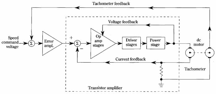 FIG. 13 Speed-control system using tachometer feedback. Tachometer
feedback; Voltage feedback
FIG. 13 Speed-control system using tachometer feedback. Tachometer
feedback; Voltage feedback
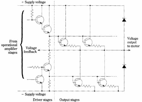
FIG. 14 Driver and output stages for speed-control system of FIG.
13. From operational amplifier stages; Voltage Output to motor; Supply
voltage Driver stages
The configuration for the driver and output stages used in the tachometer speed-control system is shown in FIG. 14. Bipolar power is made available for the motor to provide for reversal. Dual power supplies are required, as are double out puts from the op-amp stages. The output stage functions in the linear mode and can accommodate a number of paralleled transistors providing that the current-sharing emitter resistances are used, and due consideration is given the matters of drive and heat removal.