AMAZON multi-meters discounts AMAZON oscilloscope discounts
.The speed control circuit of FIG. 4 can provide a wide range of speed adjustments. At the same time, the speed regulation is generally superior to that of the inherent behavior of the motor itself. This controller was specifically developed for use with dc shunt motors. Speed torque curves obtained with a 1/8-hp dc shunt motor are shown in FIG. 5.
Unlike many thyristor motor-control schemes, this one converts the power from the ac line to dc via a bridge rectifier (Dl through D4). The motor field is permanently connected across the dc output of this bridge. The armature of the motor receives variable duty-cycle current pulses from the SCR, which interrupts the full-wave dc from the bridge rectifier. It might initially appear that there would be a commutation problem with the SCR, as is usually the case when dc is chopped or interrupted. However, this is not the case with the circuit in FIG. 4. The unidirectional current obtained from the rectifying bridge dips to zero twice each cycle, because it’s not filtered. This being the case, the SCR extinguishes its conduction twice for each full cycle of the incoming ac power. From a 60-Hz line, the SCR can be triggered into its on state 120 times per second, rather than 60, as in conventional half-wave circuits. Accordingly, it must be classified as a full-wave controller.
Note: Motor size determines types SCR, D1—D5 and thyrector
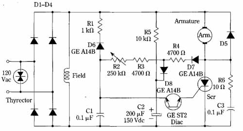
FIG. 4 Speed control for dc shunt motor. General Electric Co.
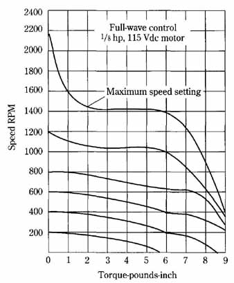
FIG. 5 Typical speed/torque curves obtained with the full-wave control
circuit. General Electric Co.
In other respects, this SCR circuit operates similarly to many other motor- speed controllers. The time that it takes timing capacitor C1 to charge to the breakdown voltage of the diac determines the triggering time of the SCR. If the SCR is triggered early in the excursion of a half-cycle of the rectified waveform, a large amount of average dc power will be delivered to the motor armature. If, however, speed adjustment control R2 is set to slow down the charging rate of capacitor C1, triggering voltage will be reached at a later time. Therefore, a relatively small amount of average dc power will flow into the armature and the motor speed will be reduced.
Although a feedback path might not be obvious in the schematic diagram, negative feedback is a major feature of this arrangement. Therefore, the motor speed not only is adjustable, but can be regulated as well. Suppose that the motor is suddenly loaded and attempts to drop its speed considerably. Such a slowdown would be ac companied by a reduction in the counter EMF, thereby enabling timing capacitor C1 to charge faster through D7, R4, R3, and R2, Triggering voltage is then developed across C1 earlier in the half cycle, and the motor armature receives a higher aver age current, thereby accelerating it to counteract the drop in speed. One should be mindful that the voltage monitored by D7 is the anode voltage of the SCR and is the output of the bridge rectifier minus the armature counter EMF. The opposite reactions occur if the motor attempts to speed up. You can now identify the feedback path as comprising D7, R4, R3, and R2.