AMAZON multi-meters discounts AMAZON oscilloscope discounts
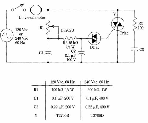
The circuit shown in FIG. 3 features a wide speed-control range, together with smooth motor performance. These desirable characteristics stem from the use of full-wave triac control and a double phase-shift network. The full-wave control enables application of nearly full power to the motor at the high end of the control range. As previously pointed out, half-wave control is a rectification process; a half- wave rectifier working over the full 180-degree of the AC half cycle can deliver only 45 percent of the average load current that would be available directly from the ac line. Another disadvantage of half-wave control arises when it’s desired to use an isolation transformer in the incoming line—the dc component that accompanies half- wave rectification tends to saturate the transformer, thereby increasing its losses and distorting the voltage waveshape in the secondary winding.
The triac does not provide full-wave rectification; its control mechanism is even better for the purpose at hand. The triac functions as would two SCRs connected back to back, but without the gating complications attending the use of dual SCRs. The voltage delivered to the load is always an ac sine wave. Variable fractions of a true sine wave are produced by varying the timing of the gate trigger signal. Because of the aforementioned wave symmetry, there is no dc component. Because rectification is not involved, a universal motor would be expected to perform much better than a dc series motor. Also, this circuit could be used to provide limited speed control to certain types of induction motors, such as the permanent-capacitor and shaded-pole types.
The double phase-shift network comprises R1, C1, R2, and C2. This network practically eliminates a disturbing hysteresis effect which characterizes single phase shift networks when a thyristor is operated at low conduction angles—this corresponds to low motor speeds. For lamp loads, the hysteresis effect is merely a nuisance; you learn to exercise patience when adjusting for dim illumination. How ever , for motor control, the effect is more serious because erratic operation will occur at low speeds. Hysteresis is due to the abrupt reduction of voltage across timing capacitor C1 when triggering occurs. Techniques for overcoming this effect involve imposing less loading on this capacitor.

FIG. 3 Triac speed-control for universal motors. General Electric Co.
The “snubber” network, R3 and C3, connected across the triac is a necessary precaution when inductive loads, such as motors, are used. Otherwise, the inductive kickback pulse developed when the triac switches to its off state can have a rate of rise that is sufficient to retrigger the triac regardless of gating conditions.