AMAZON multi-meters discounts AMAZON oscilloscope discounts
OBJECTIVES
- determine, for several types of three-phase ac induction motors, the:
- size of the conductors required for three-phase, three-wire branch circuits.
- sizes of fuses used to provide starting protection.
- disconnecting means required for the motor type.
- size of the thermal overload units required for running overcurrent protection. size of the main feeder to a motor installation.
- overcurrent protection required for the main feeder.
- main disconnecting means for the motor installation.
- use the National Electrical Code.
The work of the industrial electrician requires knowledge of the National Electrical Code requirements which govern three-phase motor installations and the ability to apply these requirements to installations. The elements of a motor circuit are illustrated in 1.
This unit outlines the procedure for determining the wire size and the proper overload and starting protection for a typical three-phase motor installation. The motor installation example consists of a feeder circuit feeding three branch circuits. Each of the three branch circuits is connected to a three-phase motor of a specified horsepower rating. The feeder circuit and the branch circuits have the necessary overcurrent protection required by the National Electrical Code.
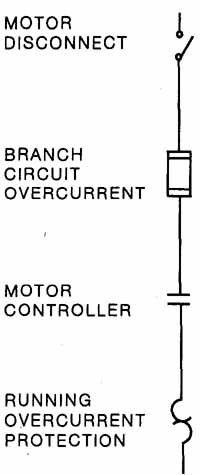
ill. 1 Line diagram of motor control system.
THREE-PHASE MOTOR LOAD
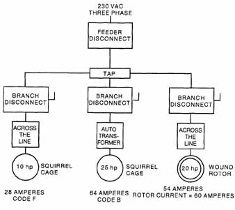
ill. 2 Branch circuit for each motor
The industrial motor installation described in this example is connected to a 230-volt, three-phase, three-wire service ( 2). The load of this system consists of the following branch circuits.
1. One branch circuit which feeds a three-phase, squirrel-cage induction motor rated at 230 volts, 28 amperes, 10 hp, with a code letter F marking.
2. One branch circuit which feeds a three-phase, squirrel-cage induction motor rated at 230 volts, 64 amperes, 25 hp, with a code letter B marking.
3. One branch circuit which feeds a three-phase, wound-rotor induction motor rated at 230 volts, 54 amperes, and 20 hp. The full-load rotor current is 60 amperes.
BRANCH CIRCUIT FOR EACH MOTOR
The values given in NEC Tables 310-16, 310-17, 310-18 and 310-19, including notes, shall be used with code book current for motors in determining ampacity of conductor and fuse size.
Three specific facts must be determined for each of the three branch circuits comprising the load of the installation.
1. The size of the conductors for each three-phase, three-wire branch circuit.
2. The fuse size to be used for short circuit protection. The fuses protect the wiring and the motor from any faults or short circuits in the wiring or motor windings.
3. The size of the thermal overload units to be used for running protection. The overload units protect the motor from potential damage due to a continued overload on the motor.
NOTE: The full-load amperes shall be taken from the motor’s nameplate only for calculating thermal overload units (See NEC Article 430-6). Other calculations are based on code book rated values from 430-148, 149, 150.
BRANCH CIRCUIT 1
The first branch circuit feeds a three-phase, squirrel-cage induction motor. The nameplate data of this motor is as follows:
Squirrel-Cage Induction Motor |
|
Volts 230 Phase 3 Code Letter F 10 Horsepower |
Amperes 28 Speed 1,735 r/min Frequency 60 Hertz Temperature Rating 40° Celsius |
Conductor Size
Section 430-22(a) of the Code states that branch-circuit conductors supplying a single motor shall have a carrying capacity equal to not less than 125 percent of the full-load current rating of a motor. This general rule may be modified according to Table 430-22 (a) Exception for certain special service classifications.
The following procedure is used to determine the size of the conductors of the branch circuit feeding the 10-hp motor.
a. The 10-hp motor has a full-load current rating of 28 amperes. According to Section 430-152:
28 x 125% = 35 amperes
b. Using 35 amps and referring to Table 310—16, a proper size conductor is selected. This process requires the electrician to determine the temperature ratings of each termination used second the ampere rating of the equipment circuit. According to NEC Article 110—14(c), the temperature rating of the conductor, used to determine the ampere capacity(ampacity), must not exceed the temperature rating of any of the connections. Unless all the terminations are marked for a higher temperature, the column in 310—16 marked 60-degree-C is selected to determine the conductor ampacity. Even if using a standard building wire THHN, the conductor size is #8 in the 60-degree-C column.
c. Table C1 in NEC Section C indicates that 3 #8 THHN conductors will fit in a 1/2 inch conduit.
The squirrel-cage induction motor is to be connected directly across the rated line voltage through an across-the-line motor starter. The branch-circuit, short circuit and ground fault protection for this motor consists of three standard nontime-delay fuses enclosed in a safety switch located on the line side of the magnetic starter. According to Section 430-1 09 of the Code, this switch shall be a motor-circuit switch with a horse power rating, a circuit breaker, or a molded case switch and shall be a listed device.
NOTE: The Underwriters’ Laboratories, Inc. Electrical Construction Materials List states that “some enclosed switches have dual horsepower ratings, the larger of which is based on the use of fuses with time delay appropriate for the starting characteristics of the motor. Switches with such horsepower ratings are marked to indicate this limitation and are tested at the larger of the two ratings.”
Motor Branch-Circuit Protection
The branch-circuit short circuit and ground fault protection for a three-phase, squirrel-cage induction motor marked with the code letter F is given in Table 430-152. For the branch circuit 1 motor being considered, the motor circuit overcurrent device shall not exceed 300 percent of the full-load current of the motor (nontime-delay fuses). Article 430-52 with exceptions applies to Table 430-152.
The branch-circuit fuse protection for the branch circuit feeding the squirrel-cage motor is:
Since the 10-hp motor has a full-load current rating of 28 amperes, and given the appropriate value from Table 430-152:
28 x 300%=84 amperes
Section 430-52 states that if the values for branch-circuit protective devices as deter mined using the percentages in Table 430-1 52 don't correspond to the standard device sizes or ratings, then the next larger size rating or setting should be used.
However, Section 240-6 of the Code indicates that the next larger standard size fuse above 84 amperes is 90 amperes. Standard nontime-delay cartridge fuses rated at 90 amperes may be used as the branch-circuit protection for this motor circuit.
The branch circuit, short circuit, and ground fault protection may also be calculated using a time-delay fuse. Referring to Table 430—152, the second column is selected and 175% of 28 amps is calculated (1.75 x 28 = 49 amps). The next larger size is used: in this example, 50 amp fuses would be the choice. The code does allow the electrician to increase the size of the fuse according to the exceptions to 430—52 c(1).
Three-Pole, Three-Fuse, 230-Volt Ac Safety Switches |
||
Amperes |
Approximate Manufacturer Horsepower Ratings Standard |
Maximum |
30 60 100 200 400 |
3 7 1/2 15 25 50 |
7 1/2 15* 30* 60* 100* |
ill. 3 Table for safety switches
Disconnecting Means
According to the table for safety switches ( 3) the disconnecting means for this 10-hp motor is a 15-hp, 1 00-ampere safety switch in which the 90-ampere fuses are installed.
Since these safety switches are dual rated, it's permissible to install a 60-ampere safety switch having a maximum rating of 15 hp if the time-delay fuses are appropriate for the starting characteristics of the motor. The size of the time-delay fuses installed in the safety switch depends on the degree of protection desired and the type of service required of the motor. Time-delay fuses ranging in size from 35 amperes to 60 amperes may be installed in the safety switch.
Running Overcurrent Protection
The running overcurrent protection consists of three current monitors, usually thermal, housed in the across-the-line motor starter. (See the note following Table 430-37 of the Code for an exception to this statement.)
Section 430-32(a) (1) of the Code states that the running overcurrent protection (motor and branch circuit overload protection) for a motor shall trip at not more than 125 percent of the full-load current (as shown on the nameplate) for motors with a marked temperature rise not over 40 degrees Celsius.
The trip current of the thermal units used as running overcurrent protection is:
28 x 125% = 35 amperes
When the selected overload relay isn't sufficient to start the motor or to carry the load, Section 430-3 4 permits the use of the next higher size or rating, but must trip at no more than 140 percent of the full-load motor current.
BRANCH CIRCUIT 2
A second branch circuit feeds a three-phase, squirrel-cage induction motor. The nameplate data for this motor is as follows:
Squirrel-Cage Induction Motor |
|
Volts 230 Phase 3 Code Letter B |
Amperes 64 Speed 1,740 r/min Frequency 60 Hertz 25 Horsepower Temperature Rating 40-deg Celsius |
Conductor Size
The following procedure is used to determine the size of the conductors of the branch circuit feeding the 25-horsepower motor.
a. The 25-hp motor has a full-load current rating of 68 amperes (see NEC Table 430-150). (According to Code Section 430-22(a), 125% is needed for ampacity):
68 x 125% = 85 amperes
b. Table 310-1 6 indicates that a No. 3 Type TW or THHN copper conductor or a No. 3 Type THW conductor. (Assume 60° C terminations).
c. Table C1 of Section C shows that three No. 3 TW or THW conductors may be installed in a 1 1/4-inch conduit. A 1-inch conduit's required for three No. 3 THHN conductors.
NOTE: Section 360-4F(c) of the Code requires that where conductors of No. 4 size or larger enter an enclosure, an insulating bushing or equivalent must be installed on the conduit.
Motor Branch-Circuit Protection
The 25-hp squirrel-cage induction motor is to be started using an autotransformer. The branch-circuit overcurrent protection for this motor circuit consists of three non- time-delay fuses located in a safety switch mounted on the line side of the starting compensator.
For a squirrel-cage induction motor which is marked with code letter B and which is being used with a starting compensator, Table 430-152 of the Code requires that the branch-circuit overcurrent protection not exceed 300 percent of the full-load current of the motor.
The branch-circuit overcurrent protection for the branch circuit feeding this motor is:
Since the 25-hp motor has a full-load current rating of 68 amperes (NEC Table 43 0-150),
68 x 300% = 204 amperes
Section 240-6 does not show 204 amperes as a standard size for a fuse. However, Section 430-52 permits the use of a fuse of the next higher size if the calculated size isn't a standard size. In this case, 200 amperes should be attempted. Therefore, three 200 ampere nontime-delay fuses can be used as the branch-circuit protection for this motor.
Disconnecting Means
According to the table for safety switches in figure 2 1—3, the disconnecting means for the 25-hp motor is a 25-hp, 200-ampere safety switch in which the 200 ampere fuses are installed.
Time-delay fuses may be installed in safety switches. In this example, 175% x 68A = 11 9A. 125 fuses are the next largest size and may be used according to exceptions to 430-52. The safety switch would be the same size.
Running Overcurrent Protection (Motor and Branch Circuit Overload Protection)
The running overcurrent protection consists of three magnetic overloads located in the starting compensator. According to the nameplate, the motor has a full-load current rating of 64 amperes. The current setting of the magnetic overload units is set to trip at
64 x 125% = 80 Amperes (trip current)
BRANCH CIRCUIT 3
A third branch circuit feeds a three-phase, wound-rotor induction motor. The name plate data for this motor is as follows:
Wound-Rotor Induction Motor |
|
Volts 230 Phase 3 Frequency 60 Hertz |
Stator Amperes 54 Rotor Amperes 60 20 Horsepower Temperature Rating 40-deg Celsius |
Conductor Size (Stator)
The following procedure is used to determine the size of the conductors of the branch circuit feeding the 20-horsepower motor.
a. The 20-hp motor has a full-load current rating of 54 amperes. According to NEC Section 430-22(a), and Table 430-150, 54 x 125% = 67.5 amperes
b. Table 310-1 6 indicates that a No. 4 Type TW, THW, THHN conductor (70 amperes).
c. Tables C1 of Section C show that three No. 4 TW or THW, or THHN conductors may be installed in a 1-inch conduit.
NOTE: Article 300-4F(c) requires that where conductors of No. 4 size or larger enter an enclosure, an insulating bushing or equivalent must be installed on the conduit.
Motor Branch-Circuit Protection
The 20-hp wound-rotor induction motor is to be started by means of an across- the-line magnetic motor switch. This motor starter applies the rated three-phase voltage to the stator winding. Speed control is provided by a manual drum controller used in the rotor or secondary circuit. All of the resistance of the controller is inserted in the rotor circuit when the motor is started. As a result, the inrush starting current to the motor is less than if the motor were started at the full voltage.
The branch-circuit overcurrent protection of a wound-rotor induction motor is required by Table 430-152 of the Code not to exceed 150 percent of the full-load running current of the motor.
The branch-circuit overcurrent protection for the branch circuit feeding this motor is:
The full-load current equals 54 amperes for a 20-hp wound-rotor motor
54 x150% = 81 amperes
Section 240-6 does not show 81 amperes as a standard fuse size. Article 430-52 allows the next larger size. A 90A fuse should be chosen.
Disconnecting Means
According to the table for safety switches in figure 14-3, the disconnecting means for the 20 hp motor is a 25-hp, 200-ampere safety switch. Reducers must be installed in this switch to accommodate the 90-ampere fuses required for the motor branch circuit protection. Because of the dual rating of these safety switches, it's permissible to use a 100-ampere switch having a maximum rating of 30 hp. In this case, standard 90-ampere nontime-delay fuses or 90-ampere time-delay fuses may be installed.
Running Overcurrent Protection (Motor Overload Protection)
The running overcurrent protection consists of three thermal overload units located in the across-the-line magnetic motor starter (except as indicated in the note following Table 430-3 7). According to the nameplate, the motor has a full-load current rating of 54 amperes. The rated trip current of each thermal unit's:
54 x125% = 67.5 amperes
Conductor Size (Rotor)
The rotor winding of the 20-hp, wound-rotor induction motor is rated at 60 amperes. The following procedure is used to determine the size of the conductors for the secondary circuit from the rotor slip rings to the drum controller.
a. Section 430-23 (a) requires that the conductors connecting the secondary of a wound-rotor induction motor to its controller have a current-carrying capacity not less than 125 percent of the full-load secondary current of the motor for continuous duty.
60 x125% = 75 amperes
b. Table 310-1 6 indicates that several types of copper conductors can be used: No. 3 Type TW, Type THW, or Type THHN, assuming 60° terminations.
c. Table C1 of Section C shows that three No. 3 TW conductors can be installed in a 1¼ inch conduit. A 1¼-inch conduit's required if three No. 3 THW conductors are used. A 1-inch conduit's required for three No. 3 THHN wires.
NOTE: Article 300-4F(c) requires the use of insulating bushings or equivalent on all conduits containing conductors of No. 4 size or larger entering enclosures. If the resistors are mounted outside the speed controller, the current capacity of the conductors between the controller and the resistors shall be not less than the values given in Table 430-23(c).
E.g., the manual speed controller used with the 20-hp wound-rotor induction motor is to be used for heavy intermittent duty. Section 430-23(c) requires that the conductors connecting the resistors to the speed controller have an ampacity not less than 85 percent of rated rotor current.
60 x 85% = 51 amperes
Table 310-1 6 indicates that 51 amperes can be carried safely by No. 6 wire. As a result, the temperatures generated at the resistor location are an important consideration.
Section 430-32(d) states that the secondary circuits of wound-rotor induction motors, including the conductors, controllers and resistors, shall be considered as protected against overload by the motor running overcurrent protection in the primary or stator circuits, Therefore, no overcurrent protection is necessary in the secondary rotor circuit.
MAIN FEEDER
When the conductors of a feeder supply two or more motors, the required wire size is determined using Code rules. Section 430-24 of the Code states that the feeder shall have an ampacity of not less than 125 percent of the full-load current of the highest rated motor of the group plus the sum of the full-load current ratings of the remaining motors in the group. The full-load current of the motor is taken from NEC Table 430-150.
The motor with the largest full-load running current is the 25-hp motor. This motor has a full-load current rating of 68 amperes. The main feeder size, then, in compliance with Section 430-24, is:
68 x 125% = 85 amperes
Then: 85 + 54 + 28 = 167 amperes.
Table 310-1 6 indicates that No. 4/0 Type TW or Type THHN copper conductors can be used when using 600 terminations.
Table C1 of Section C show that three No. 4/0 TW conductors can be installed in 2-inch conduit. Three No. 4/0 THHN conductors can be installed in a 2-inch conduit.
Main Feeder Short-Circuit Protection
Section 430-62 (a) states that a feeder which supplies motors shall be provided with overcurrent protection. The feeder overcurrent protection shall not be greater than the largest current rating of the branch-circuit protective device for any motor of the group, based on Table 430-152, plus the sum of the full-load currents of the other motors of the group.
The branch circuit feeding the 25-hp motor has the largest value of overcurrent protection. This value, as determined from Table 430-152, is 170 amperes (68 x 300 or 200 amperes.)
The full-load current rating of the 20-hp motor is 54 amperes, and the full-load current rating of the 10-hp motor is 28 amperes. The size of the fuses to be installed in the main feeder circuit shall not be greater than the sum of 200 + 54 + 28 = 282 amperes.
Therefore, three 250-ampere nontime-delay fuses are used for the feeder circuit. This procedure should be in conformance with Example 8, section 9 of the Code. Exceptions may be made if the fuses don't allow the motor to start or run.
Main Disconnecting Means
Section 430-1 09 lists several exceptions to the ruling that the disconnecting means shall be a motor-circuit switch, rated in horsepower, or a circuit breaker. The disconnecting means shall have a carrying capacity of at least 115 percent of the sum of the current ratings of the motors, Section 430-110 (c1 and 2). Therefore, the 250 ampere fuses required as the overcurrent protection for the main feeder are installed in a 400-ampere safety switch.
Wire types and sizes are selected by the ambient temperatures of the place of installation and the economics of the total installation, such as the minimum size conduits, cost of the wire sizes, and the cost of the labor to install the different selections.
SUMMARY
The motor installation is one of the hardest calculations to perform and get all the components correct, in the proper location, and at the correct size. The code book guides you through the main components of the calculation but you must know where to look and how to apply the proper codes. There are many facets to the correct installation including: feeder and feeder protection, branch circuit and branch protection, conductor sizes and overcurrent protection, running overcurrent protection and secondary circuit protection.
REVIEW QUIZ
A feeder circuit feeds three branch motor circuits. Branch motor circuit No. 1 has a load consisting of an induction motor with the following nameplate data:
No. 1:
Squirrel-Cage Induction Motor |
|
230 Volts 3 Phase 5 Horsepower |
15 Amperes 60 Hertz Code Classification D Temperature Rating 40° Celsius |
Branch motor circuit No. 2 has a load consisting of an induction motor with the following nameplate data: (This motor is equipped with an autotransformer starting compensator.):
No. 2:
Wound-Rotor Induction Motor |
|
230 Volts 3 Phase 7.5 Horsepower |
40 Amperes 60 Hertz Code Classification F Temperature Rating 40° Celsius |
Branch motor circuit No. 3 has a load consisting of a wound-rotor induction motor with the following nameplate data:
Squirrel-Cage Induction Motor |
|
230 Volts 3 Phase 15 Horsepower |
22 Stator Amperes 26 Rotor Amperes 60 Hz Temperature Rating 40° Celsius |
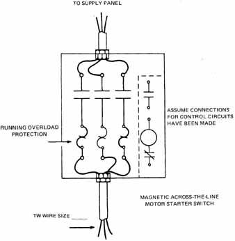
1. Refer to the following diagram.
a. Determine the running overload protection in amperes required for the motor in branch circuit No. 1.
b. Determine the appropriate wire size (TW). (Insert the answers on the diagram.)
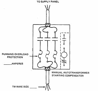
Fig q1 ASSUME CONNECTIONS FOR CONTROL CIRCUIT HAVE BEEN MADE;
MAGNETIC ACROSS-THE-LINE MOTOR STARTER SWITCH
2. Refer to the following diagram.
a. Determine the running overload protection in amperes required for the motor in branch circuit No. 2.
b. Determine the appropriate wire size of the copper TW conductors. Note that the 15-hp squirrel-cage induction motor in this circuit's started by means of a starting compensator.
(Insert the answers on the diagram.)
ill. q2
3. Refer to the following diagram.
a. Determine the running overload protection in amperes required for the motor in branch circuit No. 3.
b. Determine the appropriate wire size of the copper conductors. (Insert the answers on the diagram.)
c. Determine the size of the conductors required for the secondary circuit of the wound-rotor induction motor in branch circuit No. 3. The secondary or rotor circuit feeds between the slip rings of the wound rotor and the speed controller. Indicate the size of the conduit. Use TW conductors.
ill. q3
4. Refer to the following diagram.
a. Determine the current rating in amperes of the fuses (nontime-delay) used as overload protection for the main feeder circuit shown in the diagram.
b. Determine the TW conductor size for the main feeder switch. (Insert the answers on the diagram.)
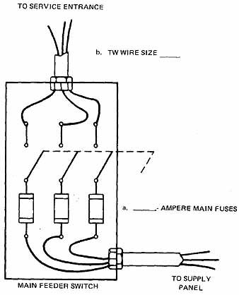
ill. q4
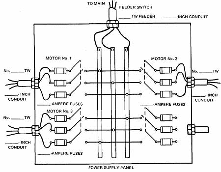
5. Refer to the following diagram.
a. Using 1W-type copper conductors, determine the size of the conductors and conduit required for the main feeder circuit which feeds the three branch motor circuits. Indicate the sizes on the diagram.
b. Determine the size of fuses in amperes required for the starting overload protection for each of the branch circuits.
Motor Circuit No. 1 ______
Motor Circuit No. 2 ______
Motor Circuit No. 3 ______
(Insert the answers on the diagram.)
c. Using 1W-type copper conductors, determine the size of rigid conduit required for each of the three branch circuits.
Motor Circuit No. 1 _____
Motor Circuit No. 2 _____
Motor Circuit No. 3 _____
(Insert the answers on the diagram.)
ill. q5