AMAZON multi-meters discounts AMAZON oscilloscope discounts
OBJECTIVES
• describe the basic operation of the following types of induction motors:
- split-phase motor (both single and dual voltage)
- capacitor start, induction run motor (both single and dual voltage)
- capacitor start, capacitor run motor with one capacitor
- capacitor start, capacitor run motor with two capacitors
- capacitor start, capacitor run motor having an autotransformer with one capacitor
• compare the motors in the listing of objective 1 with regard to starting torque, speed performance, and power factor at the rated load.
The two principal types of single-phase induction motors are the split-phase motor and the capacitor motor. Both types of single-phase induction motors usually have a fractional horsepower rating. The split-phase motor is used to operate such devices as washing machines, small water pumps, oil burners, and other types of small loads not requiring a strong starting torque. The capacitor motor generally is used with devices requiring a strong starting torque, such as refrigerators and compressors. Both types of single-phase induction motors are relatively low in cost, have a rugged construction; and exhibit a good operating performance.
CONSTRUCTION OF A SPLIT-PHASE INDUCTION MOTOR
The split-phase induction motor basically consists of a stator, a rotor, a centrifugal switch located inside the motor, two end shields housing the bearings that support the rotor shaft, and a cast steel frame into which the stator core is pressed. The two end shields are bolted to the cast steel frame. The bearings housed in the end shields keep the rotor centered within the stator so that it will rotate with a minimum of friction and without striking or rubbing the stator core.
The stator for a split-phase motor consists of two windings held in place in the slots of a laminated steel core. The two windings consist of insulated coils distributed and connected to make up two windings spaced 90 electrical degrees apart. One winding is the running winding and the second winding is the starting winding.
The running winding consists of insulated copper wire. It is placed at the bottom of the stator slots. The wire size in the starting winding is smaller than that of the running winding. These coils are placed on top of the running winding coils in the stator slots nearest to the rotor.
Both the starting and running windings are connected in parallel to the single-phase line when the motor is started. After the motor accelerates to a speed equal to approximately two-thirds to three-quarters of the rated speed, the starting winding is disconnected automatically from the line by means of a centrifugal switch.
The rotor for the split-phase motor has the same construction as that of a three-phase, squirrel-cage induction motor. That is, the rotor consists of a cylindrical core assembled from steel laminations. Copper bars are mounted near the surface of the rotor. The bars are brazed or welded to two copper end rings. In some motors, the rotor is a one-piece cast aluminum unit.
ill 1 shows a typical squirrel-cage rotor for a single-phase induction motor. This type of rotor requires little maintenance since there are no windings, brushes, slip rings, or commutators. Note in the figure that the rotor fans are a part of the squirrel-cage rotor assembly. These rotor fans maintain air circulation through the motor to prevent a large increase in the temperature of the windings.
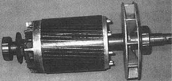
ill. 1 Cast aluminum squirrel-cage rotor.
The centrifugal switch is mounted inside the motor. The centrifugal switch disconnects the starting winding after the rotor reaches a predetermined speed, usually two-thirds to three-quarters of the rated speed. The switch consists of a stationary part and a rotating part. The stationary part is mounted on one of the end shields and has two contacts which act like a single-pole, single-throw switch. The rotating part of the centrifugal switch is mounted on the rotor.
A simple diagram of the operation of a centrifugal switch is given in figure 2. When the rotor is at a standstill, the pressure of the spring on the fiber ring of the rotating part keeps the contacts closed. When the rotor reaches approximately three-quarters of its rated speed, the centrifugal action of the rotor causes the spring to release its pressure on the fiber ring and the contacts open. As a result, the starting winding circuit's disconnected from the line. ill 3 is a typical centrifugal switch used with split-phase induction motors.
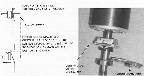
ill. 2 Diagram shows the operation of a centrifugal switch:
rotor at standstill centrifugal switch closed; rotor at normal speed centrifugal
force set up in switch mechanism causes collar to move and allows switch
contacts to open. ill. 3 Centrifugal switch mechanism with
switch removed.
Principle of Operation
When the circuit to the split-phase induction motor is closed, both the starting and running windings are energized in parallel. Because the running winding consists of a relatively large size of wire, its resistance is low. Recall that the running winding is placed at the bottom of the slots of the stator core. As a result the inductive reactance of this winding is comparatively high due to the mass of iron surrounding it. Since the running winding has a low resistance and a high inductive reactance, the current of the running winding lags behind the voltage approximately 90 electrical degrees.
The starting winding consists of a smaller size of wire; therefore, its resistance is high. Since the winding is placed near the top of the stator slots, the mass of iron surrounding it's comparatively small and the inductive reactance is low. Therefore, the starting winding has a high resistance and a low inductive reactance. As a result, the current of the starting winding is nearly in phase with the voltage.
The current of the running winding lags the current of the starting winding by approximately 30 electrical degrees. These two currents spaced 30 electrical degrees apart pass through these windings and a rotating magnetic field is developed. This field travels around the inside of the stator core. The speed of the magnetic field is determined using the same procedure given for a three-phase induction motor.
If a split-phase induction motor has four poles on the stator windings and is connected to a single-phase, 60-Hz source, the synchronous speed of the revolving field is:
S = 120 x f / 4
S=synchronous speed
f = frequency in hertz
S = 120 x 60 / 4 = 1,800 r/min
As the rotating stator field travels at the synchronous speed, it cuts the copper bars of the rotor and induces voltages in the bars of the squirrel-cage winding. These induced voltages set up currents in the rotor bars. As a result, a rotor field is created which reacts with the stator field to develop the torque which causes the rotor to turn.
As the rotor accelerates to the rated speed, the centrifugal switch disconnects the starting winding from the line. The motor then continues to operate using only the running winding. ill 4 illustrates the connections of the centrifugal switch at the instant the motor starts (switch closed) and when the motor reaches its normal running speed (switch open).
A split-phase motor must have both the starting and running windings energized when the motor is started. The motor resembles a two-phase induction motor in which the currents of these two windings are approximately 90 electrical degrees out of phase. The voltage source, however, is single-phase; therefore, the motor is called a split-phase motor because it starts like a two-phase motor from a single-phase line. Once the motor accelerates to a value near its rated speed, it operates on the running winding as a single-phase induction motor.
If the centrifugal switch contacts fail to close when the motor stops, then the starting winding circuit's still open. When the motor circuit's reenergized, the motor won't start. The motor must have both the starting and running windings energized at the instant the motor circuit's closed to create the necessary starting torque. If the motor does not start but simply gives a low humming sound, then the starting winding circuit's open. Either the centrifugal switch contacts are not closed, or there is a break in the coils of the starting windings. This is an unsafe condition. The running winding will draw excessive current and , therefore, the motor must be removed from the line supply.
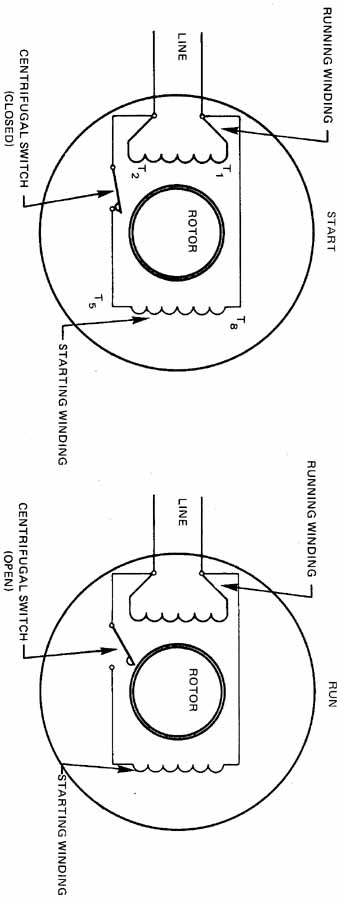
ill. 22-4 Connections of the centrifugal switch at start and at run. Split-phase induction motor: the centrifugal switch opens at approximately
75 percent of rated speed the starting winding has high resistance and low inductive reactance. The running winding has low resistance and high
inductive reactance. (produces 45-deg – 50-deg phase angle for starting
torque.)
If the mechanical load is too great when a split-phase motor is started, or if the terminal voltage applied to the motor is low, then the motor may fail to reach the speed required to operate the centrifugal switch.
The starting winding is designed to operate across the line voltage for a period of only three or four seconds while the motor is accelerating to its rated speed. It is important that the starting winding be disconnected from the line by the centrifugal switch as soon as the motor accelerates to 75 percent of the rated speed. Operation of the motor on its starting winding for more than 60 seconds may burn the insulation on the winding or cause the winding to burn out.
To reverse the rotation of the motor, simply interchange the leads of the starting winding ( 5). This causes the direction of the field set up by the stator windings to become reversed. As a result, the direction of rotation is reversed. The direction of rotation of the split-phase motor can also be reversed by interchanging the two running winding leads. Normally, the starting winding is used for reversing.
Single-phase motors often have dual-voltage ratings of 115 volts and 230 volts. To obtain these ratings the running winding consists of two sections. Each section of the winding is rated at 115 volts. One section of the running winding is generally marked T and T and the other section is marked T and T If the motor is to be operated on 230 volts, the two 115-volt windings are connected in series across the 230-volt line. If the motor is to be operated on 115 volts, then the two 115-volt windings are connected in parallel across the 115-volt line.
ill. 5 Reversing direction of rotation on split-phase induction
motor.
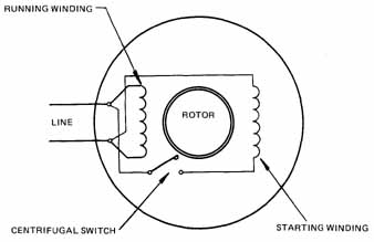
The starting winding, usually consists of only one 115-volt winding. The leads of the starting winding are generally marked T and T If the motor is to be operated on 115 volts, both sections of the running winding are connected in parallel with the starting winding ( 6).
For 230-volt operation, the connection jumpers are changed in the terminal box so that the two 115-volt sections of the running winding are connected in series across the 230-volt line ( 7). Note that the 115 volt starting winding is connected in parallel with one section of the running winding. The voltage drop across this section of the running winding is 115 volts, and the voltage across the starting winding is also 115 volts.
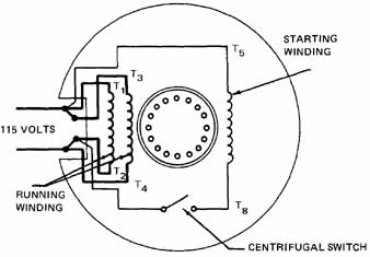
ill. 6 Dual-voltage motor connected for 115 volts.
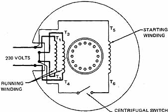
ill. 7 Dual-voltage motor connected for 230 volts.
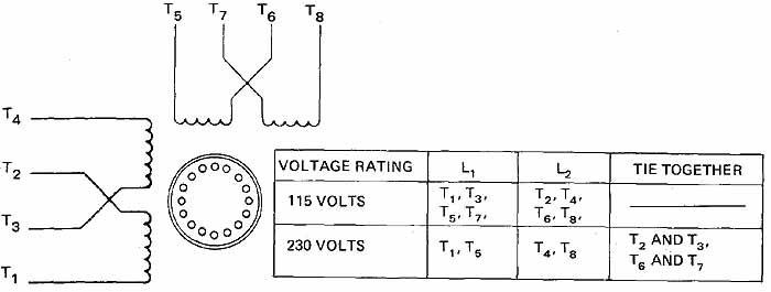
ill. 8 Winding arrangement for dual-voltage motor with two
starting and two running windings
Some dual-voltage, split-phase motors have a starting winding with two sections as well as a running winding with two sections. The running winding sections are marked T1 and T2 for one section and T3 and T4 for the other section. One section of the starting winding is marked T5 and T6 and the second section of the starting winding is marked T7 and T8.
The National Electrical Manufacturers Association (NEMA) has color coded the terminal leads. If colors are used, they should be coded as follows: T1 — blue; T2 — white; T3 — orange; T4 — yellow; T5 — black; and T6— red.
ill 7 shows the winding arrangement for a dual-voltage motor with two starting windings and two running windings. The correct connections for 115-volt operation and for 230-volt operation are given in the table illustrated in 8.
The speed regulation of a split-phase induction motor is very good. It has a speed performance from no load to full load that's similar to that of a three-phase, squirrel-cage induction motor. The percent slip on most fractional horsepower split-phase motors is from 4 percent to 6 percent.
The starting torque of the split-phase motor is comparatively poor. The low resistance and high inductive reactance in the running winding circuit, and the high resistance and low inductive reactance in the starting winding circuit cause the two current values to be considerably less than 90 electrical degrees apart. The currents of the starting and running windings in many split-phase motors are only 30 electrical degrees out of phase with each other. As a result, the field set up by these currents does not develop a strong starting torque.
CAPACITOR START, INDUCTION RUN MOTOR
The construction of a capacitor start motor is nearly the same as that of a split-phase induction motor. For the capacitor start motor, however, a capacitor is connected in series with the starting windings. The capacitor usually is mounted in a metal casing on top of the motor. The capacitor may be mounted in any convenient external position on the motor frame and , in some cases, may be mounted inside the motor housing. The capacitor provides a higher starting torque than is obtainable with the standard split-phase motor. In addition, the capacitor limits the starting surge of current to a lower value than is developed by the standard split-phase motor.
The capacitor start induction motor is used on refrigeration units, compressors, oil burners, and for small machine equipment, as well as for applications which require a strong starting torque.
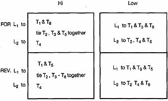
ill. 9 Two running winding connection and one start winding
connection chart.
Principle of Operation
When the capacitor start motor is connected for lower voltage and is started, both the running and starting windings are connected in parallel across the line voltage as the centrifugal switch is closed. The starting winding, however, is connected in series with the capacitor. When the motor reaches a value of 75 percent of its rated speed, the centrifugal switch opens and disconnects the starting winding and the capacitor from the line. The motor then operates as a single-phase induction motor using only the running winding. The capacitor is used to improve the starting torque and does not improve the power factor of the motor.
To produce the necessary starting torque, a revolving magnetic field must be set up by the stator windings. The starting winding current will lead the running winding current by 90 electrical degrees if a capacitor having the correct capacity is connected in series with the starting winding. As a result, the magnetic field developed by the stator windings is almost identical with that of a two-phase induction motor. The starting torque for a capacitor start motor thus is much better than that of a standard split-phase motor.
Defective capacitors are a frequent cause of malfunctions in capacitor start, induction run motors. Some capacitor failures that can occur are:
• the capacitor may short itself out, as evidenced by a lower starting torque.
• the capacitor may be “opened,” in which case the starting winding circuits will be open, causing the motor to fail to start.
• the capacitor may short circuit and cause the fuse protection for the branch motor circuit to blow. If the fuse ratings are quite high and don't interrupt the power sup ply to the motor soon enough, the starting winding may burn out.
• starting capacitors can short circuit if the motor is turned on and off many times in a short period of time. To prevent capacitor failures, many motor manufacturers recommend that a capacitor start motor be started no more than 20 times per hour. Therefore, this type of motor is used only in those applications where there are relatively few starts in a short time period.
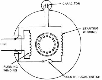
ill. 10 Connections for a capacitor start, induction motor
The speed performance of a capacitor start motor is very good. The increase in per cent slip from a no-load condition to full load is from 4 percent to 6 percent. The speed performance then is the same as that of a standard split-phase motor.
The leads of the starting winding circuit are interchanged to reverse the direction of rotation of a capacitor start motor. As a result, the direction of rotation of the magnetic field developed by stator windings reverses in the stator core, and the rotation of the rotor is reversed. (See figure 9 for reversing lead connections.)
ill 10 is a diagram of the circuit connections of a capacitor start motor before the starting winding leads are interchanged to reverse the direction of rotation of the rotor. The diagram in figure 11 shows the circuit connections of the motor after the starting winding leads are interchanged to reverse the direction of rotation.
A second method of changing the direction of rotation of a capacitor start motor is to interchange the two running winding leads. However, this method is seldom used.
Capacitor start, induction run motors often have dual-voltage ratings of 115 volts and 230 volts. The connections for a capacitor start motor are the same as those for split-phase induction motors.
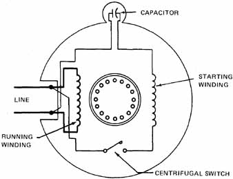
ill. 11 Connections for reversing a capacitor start, induction
run motor.
CAPACITOR START, CAPACITOR RUN MOTOR
The capacitor start, capacitor run motor is similar to the capacitor start, induction run motor, except that the starting winding and capacitor are connected in the circuit at all times. This motor has a very good starting torque. The power factor at the rated load is nearly 100 percent or unity due to the fact that a capacitor is used in the motor at all times.
There are several different designs for this type of motor. One type of capacitor start, capacitor run motor has two stator windings which are spaced 90 electrical degrees apart. The main or running winding is connected directly across the rated line voltage. A capacitor is connected in series with the starting winding and this series combination also is connected across the rated line voltage. A centrifugal switch isn't used because the starting winding is energized through the entire operating period of the motor.
ill 12 illustrates the internal connections for a capacitor start, capacitor run motor using one value of capacitance.
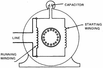
ill. 12 Connections for a capacitor start, capacitor run motor.
To reverse the rotation of this motor, the lead connections of the starting winding must be interchanged. This type of capacitor start, capacitor run motor is quiet in operation and is used on oil burners, fans, and small wood working and metal working machines.
A second type of capacitor start, capacitor run motor has two capacitors. ill 13 is a diagram of the internal connections of the motor. At the instant the motor is started, the two capacitors are in parallel. When the motor reaches 75 percent of the rated speed, the centrifugal switch disconnects the larger capacity capacitor. The motor then operates with the smaller capacitor only connected in series with the starting winding.
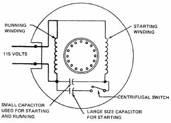
ill. 13 Connections for a capacitor start, capacitor run motor:
SMALL CAPACITOR USED FOR STARTING AND RUNNING; LARGE SIZE CAPACITOR FOR
STARTING.
This type of motor has a very good starting torque, good speed regulation, and a power factor of nearly 100 percent at rated load. Applications for this type of motor include furnace stokers, refrigerator units, and compressors.
A third type of capacitor start, capacitor run motor has an autotransformer with one capacitor. This motor has a high starting torque and a high operating power factor. ill 14 is a diagram of the internal connections for this motor. When the motor is started, the centrifugal switch connects winding 2 to point A on the tapped autotransformer. As the capacitor is connected across the maximum transformer turns, it receives maximum voltage output on start. The capacitor thus is connected across a value of approximately 500 volts. As a result, there is a high value of leading current in winding 2 and a strong starting torque is developed.
When the motor reaches approximately 75 percent of the rated speed, the centrifugal switch disconnects the starting winding from point A and reconnects this winding to point B on the autotransformer. Less voltage is applied to the capacitor, but the motor operates with both windings energized. Thus, the capacitor maintains a power factor near unity at the rated load.
The starting torque of this motor is very good and the speed regulation is satisfactory. Applications requiring these characteristics include large refrigerators and compressors.
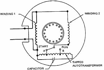
ill. 14 Connections for a capacitor start, capacitor run motor
with autotransformer
NATIONAL ELECTRICAL CODE REGULATIONS
Section 430-32(b) (1) of the National Electrical Code states that any motor of one horsepower or less which is manually started and is within sight from the starter location, shall be considered as protected against overload by the overcurrent device protecting the conductors of the branch circuit. This branch overcurrent device shall not be larger than specified in Article 430, Part D (Motor Branch Circuit, Short-Circuit and Ground-Fault Protection). An exception is that any such motor may be used at 120 volts or less on a branch circuit protected at not over 20 amperes.
A distance of more than 50 feet is considered to be out of sight from the starter location. Section 430-32(c) covers motors, one horsepower or less, automatically started, which are out of sight from the starter location or permanently installed.
Section 430-32(c) (1) states that any motor of one horsepower or less which is started automatically shall have a separate overcurrent device which is responsive to the motor current. This overload unit shall be set to trip at not more than 125 percent of the full-load current rating of the motor for motors marked to have a temperature rise not over 40 degrees Celsius or with a service factor not less than 1.15, (1.15 or higher) and not more than 115 percent for all other types of motors.
SUMMARY
The single-phase induction motor is one of the most used residential and light commercial motors. Each application will dictate the correct motor style to use. All the motors use the concept of taking one phase, or one sinewave, and shifting the effects of the cur rents through the coils to create a moving magnetic field. The split-phase and the capacitor-start motor utilize a starting switch to disconnect the starting windings from the line once the motor is up to running speed. Two-capacitor motors use multiple capacitors or variations of two value capacitors to create a starting and a running circuit. All the same NEC regulations that apply to three-phase motors still apply to single-phase motors. There are many exceptions that apply only to small-horsepower motors.
QUIZ
1. List the essential parts of a split-phase induction motor.
2. What happens if the centrifugal switch contacts fail to reclose when the motor stops?
3. Explain how the direction of rotation of a split-phase induction motor is reversed.
4. A split-phase induction motor has a dual-voltage rating of 115/230 volts. The motor has two running windings, each of which is rated at 115 volts, and one starting winding rated at 115 volts. Draw a schematic diagram of this split-phase induction motor connected for 230-volt operation.
5. Draw a schematic connection diagram of the split-phase induction motor in question 4 connected for 115-volt operation.
6. A split-phase induction motor has a dual-voltage rating of 115/230 volts. The motor has two running windings, each of which is rated at 115 volts. In addition, there are two starting windings and each of these windings is rated at 115 volts. Draw a schematic connection diagram of this split-phase induction motor connected for 230-volt operation.
7. What is the primary difference between a split-phase induction motor and a capacitor start, induction run motor?
8. If the centrifugal switch fails to open as a split-phase motor accelerates to its rated speed, what will happen to the starting winding?
9. What is one limitation of a capacitor start, induction run motor?
10. Insert the correct word or phrase to complete each of the following statements.
a. A motor of one horsepower or less which is manually started and which is within sight of the starter location is considered to be protected by the ______
b. A motor of one horsepower or less which is manually started is considered within sight of the starter location if the distance is no greater than _________
c. The capacitor used with a capacitor start, induction run motor is used only to improve the ______
d. A capacitor start, induction run motor has a better starting torque than the _________